


MODEL
8559A ADJUSTMENTS
ADJUSTMENTS
5
-
27. THIRD CONVERTER ADJUSTMENTS (Cont'd)
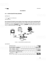
PROCEDURE:
1.
Allow
one-'lalf hour warmup time of equipment with analyzer connected to mainframe with extender
cable.
Third LO Adjustment
2. Connect frequency counter to AlOJl 300 MHz output using the BNC to SMB test cable.
3.
Adjust
AlOL12 LO
ADJ
for frequency counter indication of 300.00 MHz
+
0.1 MHz.
Second IF Bandpass Filter Alignment
4.
Disconnect blue cable
AlOWl at second converter output connector A5J2.
5.
Set sweep oscillator controls for an output of 321.4 MHz at
0 dBm (measured directly at output of sweep
oscillator). Use the frequency counter and spectrum analyzer to set the output frequency and amplitude.
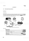
6.
Connect output through 10 and 20 dB attenuators to cable disconnected in step 4, using the BNC to SMB
test cable and SMB male to SMB male adapter.
7.
Place analyzer on right side and connect test cable to Third Converter 21.4 MHz output connector. If
connector is not present (some early instruments were not so supplied), it is necessary to solder a coaxial
cable to
XAlOPl pin 18 and ground (center conductor of coaxial cable to XAlOPl and shield to ground).
8. Connect test cable or soldered cable to
8569B spectrum analyzer input.
9.
Set
8569B spectrum analyzer controls as follows:
...............................................................
TUNING 21.4 MHz
RESBW
.................................................................
300kHz
.....................................................
FREQ SPAN/DIV 1 MHz/DIV
INPUTATTEN
.............................................................
10dB
........................................................
REF LEVEL dBm
-
10 dBm
Amplitudescale
........................................................
10dBLOG
..........................................................
TIME/DIV 1 mSEC/DIV
10.
Set HP
8559A RES BW to 1 kHz and TRIGGER to FREE RUN.
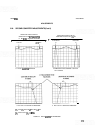
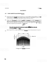
11.
Center the 21.4 MHz signal on the
8569B spectrum analyzer, adjust reference level to place signal within
top division on CRT, then change scale to 1
dB/DIV. Adjust REF LEVEL FINE to place signal peak in
upper half of display.
12. Set function generator controls for a 200 Hz triangle wave output and connect to sweep oscillator RF
Plug-
In rear
-
panel FM input. Set FM/NORM/PL switch to FM.