


MODEL
8559A
SERVICE
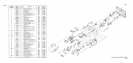
INSTALLATION OF FRONT SWITCH ASSEMBLY INTO HP 8559A CHASSIS
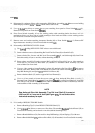
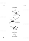
9. Set Front Switch Assembly into place in chassis, being careful not to bend semi
-
rigid cables or pinch wires
or ribbon cables. Attach Front Switch
Diecast (1) to left and right side gussets with four screws.
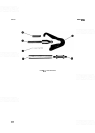
10. Connect four wires (0,916,918,923) to correspondingly
-
labelled pins in Front Switch Board A2A1.
1 1.
Attach DPM Driver Assembly A1A2 to diecast with one Screw.
12.
Connect 10
-
conductor Ribbon Cable (46) to DPM Driver Assembly AlA2.
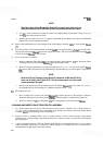
13. Connect the two 40-conductor Ribbon Cables A2Al W 1 (46) and A2A1 W2 (47) to Motherboard Assembly
A16.
14.
Use a
5/16-inch open
-
end wrench to carefully connect Semi
-
rigid Cable W2 from the Input Attenuator to
the First Mixer.
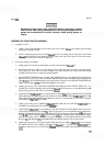
15. Use special
9/16-inch nut driver to install CAL OUTPUT connector to front panel with one dress nut.
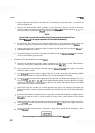
16. Slide HP
8559A into display mainframe, turn instrument ON, and verify proper operation of all controls.