


/
--
ADJUSTMENTS
5
-
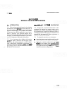
17.
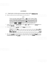
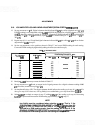
POWER SUPPLY CHECKS AND ADJUSTMENTS (SERIAL PREFIX 2236A)
REFERENCE:
A7,
A8, A9 Schematics
DESCRIPTION:
The
+
14.5V and
-
10V supplies on Frequency Control Assembly A7 are adjusted. The
-
12.OV supply on A7
is checked for proper dc output with less than
+
50 mV variation when tuning the HP 8559A from 0 to 3 GHz.
The
+
10.OV supply on Sweep Generator/Bandwidth Control Assembly
A9
is adjusted and the VO (Varactor
Offset) voltage on Marker Assembly A8 is adjusted. The
+
10.OV supply and VO voltage must be adjusted
during the first five minutes after the spectrum analyzer is turned on (cold instrument). However, the
+
14.5V
and
-
10.OV supplies must be adjusted first.
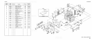
DISPLAY DIGITAL VOLTMETER
.
.
SPECTRUM
EXTENDER
ASSEMBLY
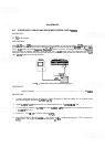
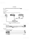
FIGURE
51.
POWER SUPPLY CHECKS AND ADJUSTMENTS TEST
SETUP
EQUIPMENT:
Digital Voltmeter
.
.
.
. . . . . . . .
.
.
. .
. .
. .
.
. .
. .
. . .
.
.
.
.
.
.
.
.
.
.
.
.
.
. .
.
. . .
.
.
.
,
. .
.
.
.
.
HP
349OA
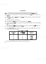
PROCEDURE:
1. Connect equipment as shown in Figure 5-1. Install Frequency Control Assembly A7 on extender board
and connect digital voltmeter to
A7TP3
+
14.5y
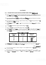
2.
Adjust A7R52
+
14.5V adjustment for
a
voltmeter indication of
+
14.500
k
0.002 volts.
3. Connect digital voltmeter to
A7TP2 and adjust A7R55
-
10V adjustment for a voltmeter indication of
-
10.000
*
0.005 volts.
4. Check for
-
12.0
*
0.1V at collector (base) of A7Ql.
5. Select FREQUENCY BAND
GHz
.01- 3 and tune from 0 to
3
while monitoring the
-
12V at collector of
A7Q1. The
-
12V supply should not vary more than
*
50 mY