


MODEL 8559A
PERFORMANCE TESTS
PERFORMANCE TESTS
4
-
19.
FREQUENCY RESPONSE (Cont'd)
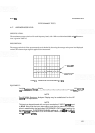
4. Adjust spectrum analyzer TUNING control for a FREQUENCY GHz readout of 0.100. Set sweep oscilla
-
tor to CW with frequency of 100 MHz and use CW control to center signal on spectrum analyzer display.
5.
Calibrate and zero power sensor and meter. Disconnect power splitter from 20
-
dB attenuator and connect
to power sensor. Adjust sweep oscillator POWER LEVEL control for a power meter indication of
-
8
dBm.
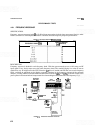
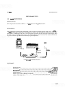
6.
Connect output of power splitter through 20
-
dB attenuator directly (do not use cable) to spectrum analyzer
input. Select Amplitude Scale setting of 1
dB/DIV, and adjust REF LEVEL FINE control as necessary to
place peak of 100 MHz signal at center horizontal graticule line of spectrum analyzer display.
7.
Adjust spectrum analyzer TUNING control for a FREQUENCY GHz readout of 0.060. Adjust sweep
oscillator CW control for
60
MHz signal, centered on spectrum analyzer display.
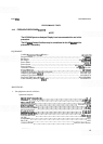
8.
Set sweep oscillator AF control for 100 MHz sweep. Adjust spectrum analyzer display PERSISTENCE
control fully clockwise. Adjust sweep oscillator SWEEP TIME vernier for slow sweep (30 seconds or
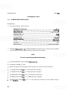
longer) and trigger a sweep. Record greatest positive and greatest negative deviation of signal peaks from
center horizontal graticule line (10 MHz to 110 MHz).
Maximum divisions
Minimum divisions
9.
Adjust spectrum analyzer TUNING control for
a
FREQUENCY GHz readout of 0.100. Set sweep oscilla
-
tor to CW with frequency of 100 MHz and use CW control to center signal on spectrum analyzer display.
10.
Set spectrum analyzer FREQ
SPAN/DIV control to F (full band) and RESOLUTION BW control to 3
MHz. Adjust TUNING control fully clockwise to position tuning marker at high end of selected frequency
band. Adjust REF LEVEL FINE control as necessary to place peak of
100 MHz signal (near LO feed-
through signal) at center horizontal graticule line of spectrum analyzer display.
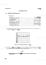
11.
Set sweep oscillator for FULL BAND (10 MHz to 2.4
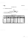
GHz) and trigger a sweep. Record greatest positive
and greatest negative deviation of signal peaks from center horizontal graticule line (10 MHz to 2.4
GHz).
Record deviation of signal peak located at 8th vertical graticule line (approximately 2.1 GHz).
Maximum divisions
Minimum divisions
8th graticule line divisions
12.
Remove 0.01
-
2.4 GHz RF Plug
-
in from sweep oscillator mainframe and replace with
2
-
22 GHz RF
Plug
-
in. Select band 4 (2.0
-
22 GHz) on HP 8620C sweep oscillator.
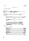
13. Set sweep oscillator to CW with frequency of 2.1
GHz and use CW control to position signal on 8th
vertical graticule line of spectrum analyzer display. Adjust ALC GAIN control for leveled sweep oscillator
output and adjust POWER LEVEL control to place signal peak at same amplitude measured in step 11.