


SERVICE
MODEL
8559A
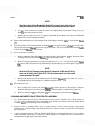
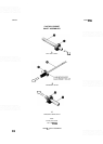
i. Inspect Attenuator Drive Rotor (8). Roll Pins
(12)
should be positioned in hole
1
and hole
9,
as
shown in Figure 8-8D.
j.
Inspect front Anticrush Drive Hub Assembly (7). Note that pin is offset to one side of drive hub;
place drive hub over right-most bushing in Front Switch
Diecast (I) with this side down (i.e., pin as
close as possible to Front Switch
Diecast) for proper switch operation.
NOTE
Correct side of front Anticrush Drive Hub
(7)
must be oriented towards Front
Switch
Diecast (1) for proper operation of Front Switch Assembly.
k. Set Attenuator Drive Rotor (8) over Anticrush Drive Hub (7) with Attenuator Drive Rotor gear
facing up. Long pin on Attenuator Drive Rotor should protrude through curved slot in
diecast.
1. Lightly grease gear end of Attenuator Shaft Assembly (18) and insert into Front Switch Diecast (1).
Place metal Washer (19) on shaft.
m.
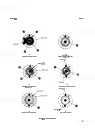
Clean contact fingers on all rotors using lint
-
free cloth and isopropyl alcohol/distilled water mixture.
All rotors should be in proper position.
3.
Installation of Front Switch Board Assembly
A2Al:
Inspect Front Switch Board Assembly. Check switch traces for dirt, grease, or wear. Check intercon-
nect wires, solder joints, pushbutton switches, and ribbon cables
(46,47).
Clean switch traces using lint
-
free cloth and isopropyl alcohol/distilled water mixture. No residue
should be visible on traces.
Use a
3/8-inch open-end wrench to tighten Hex Nut (31) and Lockwasher (30) attaching VIDEO
FILTER Potentiometer (33) and metal Washer (32) to Front Switch Board Assembly.
Use a
1/2-inch open-end wrench to tighten inner Hex Nut (28) and Washer (29) attaching Dual Tune
Pot assembly
(21,28,29, 34
-
42,44) to Front Switch Board Assembly. Note that Roll Pin (12) aligns
with hole in switch board to locate Dual Pot Bracket (39); Washer (29) between bracket and switch
board is critical to proper switch operation.
Check Dual Tune Pot assembly for smooth operation and proper gear meshing; disassemble and
lightly grease shafts if necessary. Install second Hex Nut (28) mid-way onto Coarse Tune Shaft Bush-
ing (36).
Set Front Switch Board Assembly into place on partially-assembled Front Switch Assembly and use a
Stud (53) on right-most side of switch assembly to loosely fasten switch board to Front Switch
Diecast (1).
With one Stud (53) in place but not tight, twist left side of Front Switch Board Assembly up approxi-
mately
1/8-inch to fasten switch board under Front Switch Diecast support arm (upper left corner)
and align switch shafts.
Loosely install the remaining Screws (48) used to fasten Front Switch Board Assembly to Front
Switch
Diecast
(1).
Do not overtighten screws and studs into Front Switch Diecast (1).