


PERFORMANCE TESTS
PERFORMANCE TESTS
MODEL
8559A
4
-
23.
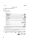
REFERENCE LEVEL ACCURACY (Cont'd)
PROCEDURE:
Step Accuracy in Log Mode
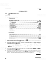
Set equipment controls as follows:
Spectrum Analyzer:
FREQUENCYBANDGHz
..................................................
.01-3
TUNING
.................................................................
30MHz
FREQ SPAN/DIV
.........................................................
100 kHz
RESOLUTION BW
................................................
30 kHz, uncoupled
INPUTATTEN
..............................................................
OdB
REFERENCE LEVEL
....................................................
-
10 dBm
REFLEVELFINE
..............................................................
0
Amplitude Scale
.........................................................
1 dB/DIV
SWEEP TIME/DIV
........................................................
AUTO
SWEEPTRIGGER
.....................................................
FREERUN
.....................................................................
ALTIF OFF
SIG IDENT
.................................................................
OFF
BLCLIP
....................................................................
OFF
VIDEOFILTER
..........................................................
2o'clock
Signal Generator:
..............................................
COUNTERMODE INT,EXPANDXlO
........................................................................
AM OFF
........................................................................
FM OFF
......................................................
FREQUENCYTUNE 30MHz
RF
..........................................................................
ON
........................................................
OUTPUTLEVEL -2dBm
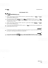
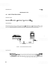
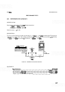
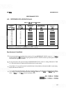
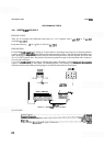
Connect equipment as shown in Figure 4
-
18 using 10
-
dB step attenuator. Set step attenuator to 0 dB and
adjust spectrum analyzer TUNING control to center 30 MHz signal on CRT Set FREQ
SPAN/DIV
control to 10 kHz and RESOLUTION BW control to 3 kHz, adjusting TUNING control as necessary to
keep signal centered on CRT
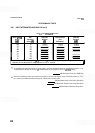
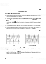
Adjust signal generator OUTPUT LEVEL control to position peak of signal 6 divisions above graticule
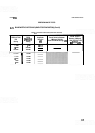
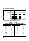
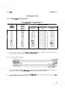
baseline. Set step attenuator and spectrum analyzer REFERENCE LEVEL control to settings indicated in
Table 4
-
10. Record deviation of signal peak from 6th division for each setting.
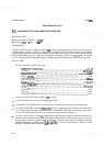
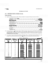
To calculate Corrected Deviation, add Step Attenuator Error (calibration data at 30 MHz) to Deviation
from 6th Division for each setting. Corrected Deviation should not exceed
+
0.5
dB from
-
10 dBm to
-
80 dBm, and should not exceed
k
1.0 dB from
-
10
dBm to
-
100 dBm. Record maximum values.