


MODEL
8559A
YIG-TUNED OSCILLATOR ASSEMBLY A6, CIRCUIT DESCRIPTION
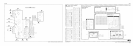
The YIG
-
Tuned Oscillator Assembly A6 consists of three parts: a sealed magnet assembly that encloses the YIG
sphere and oscillator; a bias board that uses discrete components to establish the oscillator and amplifier bias, as
well as protect the bias supply from noise and voltage overloads; and a mu
-
metal magnetic
-
shield can. Field
service of the YIG
-
Tuned Oscillator Assembly A6 is limited to replacement with a new or factory rebuilt unit.
The YIG
-
Tuned Oscillator A6 is a transistor thin
-
film microcircuit. It uses a Yttrium
-
Iron
-
Garnet (YIG) sphere
as the frequency determining structure. The YIG sphere is placed in the gap of an electromagnet to provide a
magnetic tuning structure whose field (and thereby the oscillator's frequency) is linearly proportional to the
drive current from the Frequency Control Assembly A7.
The Main coil is used for wide range sweeping and tuning with the coil current varying from approximately 69
mA
to 138
mA.
The FM coil performs these functions for narrow spans
(1
MHz/div and less) with its coil
current varying from approximately
-
18
mA
to
+
18
rnA.
YIG
-
TUNED OSCILLATOR ASSEMBLY A6, TROUBLESHOOTING
Power Holes:
Power holes that occur at the same point of the sweep in
all
bands are most commonly caused
by the YIG
-
Tuned Oscillator Assembly A6.
Power holes above 18
GHz are most commonly caused by the type
-
N RF input connector on the HP 8559A
front panel.
Residual
FM:
The primary cause of residual FM involving the first LO is the Frequency Control Assembly
A7.