


SERVICE MODEL 8559A
Pulse Shaper
(M)
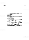
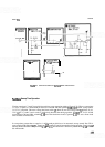
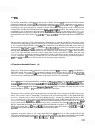
The pulse shaper circuit (block M) consists of an FET switch, a Schmitt trigger, a differentiator, and an emitter
-
-
follower (see Figure 8-36). Field-effect transistor 456, and its associated components, disconnects the base of
435 during the sweep cycle to prevent the Schmitt trigger from firing during a sweep. Transistors 434 and 435
make up the Schmitt trigger. Transistor 435 is normally off; 434 is conducting. On the positive portion of the
input signal (either video or line), 435 is driven into conduction, turning 434 off. The switching speed of 434
and 435 is increased by feedback (between the collector of 435 and the base of 434) through C13 and
R58.
When 435 switches on, the negative change at the collector is differentiated by C14 and R60 and coupled
through
436 to the emitter of 433. The negative pulse causes 433 to turn on. Zener diode VRl switching diode
CR5, and resistor R41 keep 433 on while the ramp is generated. When the ramp is completed, the circuit
returns to its dead time state until another negative trigger pulse begins a new sweep cycle.
TRIG
D
SYNC
0
I-
TO COMPARATOR
AMPL
l
F
l
ER
C15
\I
,I
A40
-
12
6V
RETRACE
BLANK
FIGURE
8-36,
SIMPLIFIED SCHEMATICOFVIDEO, LINE, AND AUTO TRIGGER MODES
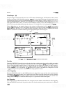
Free Run
During the FREE RUN (internally triggered) mode, the trigger switch grounds the sync line, which removes the
pulse shaper (block M) from the circuit. At the same time, the switch applies
+
15V through the trigger (TRIG)
line to voltage divider R52 and R53 (block
L).
This divider sets the voltage at the cathode of CRlO at approxi-
mately
+
1.4Y Since the voltage drops across CRlO and CR6 are equal but opposite, they cancel. For this
reason, the base of 433 is also about
+
1.4Y Transistor 433 turns on and drives the comparator to about
+
14V, initiating free run operation as described in the sweep generator section.
Video Triggering
When the TRIGGER switch is in the VIDEO position, the trigger line is open and the video signal (from the
Vertical
Driver/Blanking Assembly A15) is applied to the pulse shaper (block M) through the sync line. With the
trigger line open,
433 is held off until a negative pulse turns 433 on and begins the sweep cycle outlined in the
sweep generator description. At the end of the sweep, 433 is again held off until the next pulse.
Line Triggering
The sweep may be synchronized with the ac line voltage in the same manner
as
described for video triggering.
With the TRIGGER switch in the line position, the ac line from the mainframe power transformer is connected