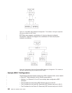
BSC Relay also supports a combination of virtual and physical multipoint
connections. Figure 32 is a diagram of a combination of virtual and physical
multipoint connections.
Sample BRLY Configuration
The following examples illustrate configuring a BRLY network similar to the network
in Figure 32. These examples use the following assumptions:
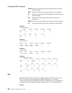
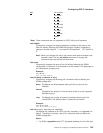
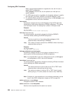
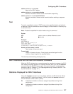
v Interface 1 on Routers A, B, and C have already been configured as BSC
interfaces.
v The IP address for the Primary BSC Device’s local port is 6.6.6.4.
v The IP address for the Router B’s Secondary BSC devices local port is 6.6.6.1.
v The IP address for the Router C’s Secondary BSC devices local port is 6.6.6.2.
┌───────────┐
│Primary BSC│
│ Device │
└───┬────┬──┘
1 ┌─┴────┴─┐ 2
│Router A│
└─┬────┬─┘
││
1││2
┌─┴────┴─┐
│Router B│
└─┬─────┬┘
││
1│ │2
┌────────┴─┐ ┌─┴─────────┐
│Secondary │ │ Secondary │
│BSC Device│ │ BSC Device│
└──────────┘ └───────────┘
Figure 31. Virtual BSC Relay Multipoint Configuration. The numbers in the figure represent
the group numbers for BSC Relay.
┌───────────┐
│Primary BSC│
│ Device │
└─────┬─────┘
1│2
┌───────────────┴────────────────┐
│ Router A │
└────┬───────────────────────┬───┘
││
1│ 2│
┌──────┴────┐ ┌────┴─────┐
│ Router B │ │ Router C │
└─┬─────────┘ └─┬────────┘
1 ├───────┐ 2 ├───────┐
┌───────┴──┐ │ ┌─────┴────┐ │
│Secondary │ │ │Secondary │ │
│BSC Device│ │ │BSC Device│ │
└──────────┘ │ └──────────┘ │
┌──┴───────┐ ┌─┴────────┐
│Secondary │ │Secondary │
│BSC Device│ │BSC Device│
└──────────┘ └──────────┘
Figure 32. Combination Virtual and Physical BRLY Multipoint Configuration. The numbers in
the figure represent the group numbers for BSC Relay.
562 MRS V3.2 Software User’s Guide
|
|
|
|
|
|
|
|
|
|
|
|


