


Reference
GB1400 User Manual 3-23
Clock, Data, and Reference Data Inputs
This section explains how to set up Analyzer clock, data, and reference data
inputs using front panel controls and Menus.
Overview
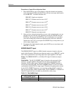
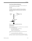
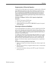
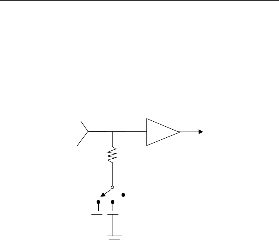
The Analyzer CLOCK, DATA, and REF DATA inputs are designed to
accommodate a wide range of output logic levels and circuit designs. An
equivalent circuit diagram of the Analyzer input section is shown in the
following figure.
50
ΩΩ
-2Vdc
AC
Input Comp
GND
Figure 3-3. Analyzer Clock and Data Input Circuits
Input Parameters
The following input parameters may be set manually by the user or automatically
by the AUTO SEARCH function:
Decision threshold (DATA, and REF DATA)
Delay (DATA and REF DATA)
Inverted or non-inverted data (DATA).
In addition, there are termination parameters that can be selected only by the
user:
Termination (CLOCK, DATA, and REF DATA)
Note that user or manual control functions may be executed locally, via front
panel controls or Menus, or remotely via the instrument's RS-232 or GPIB ports.