


Functional Overview
2-10 GB1400 User Manual
installed) when not in use—that is, when the Generator is driving single-
ended inputs.
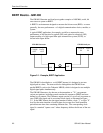
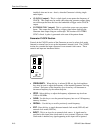
• CLOCK/4 [output]: This is a clock signal at one quarter the frequency of
CLOCK. This output may be useful when observing generator outputs using
an oscilloscope that does not have the bandwidth to trigger on the CLOCK
output.
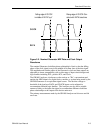
• PATTERN SYNC [output]: This is a pulse that occurs once per pattern
frame. This output may be useful as a trigger signal when observing the
Generator data output using an oscilloscope. The location of PATTERN
SYNC is fixed. A pulse is generated at the start of the pattern frame.
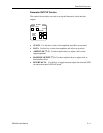
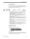
Generator CLOCK Section
Controls in the CLOCK section of the Generator are used to select clock mode
(internal or external) and to set up the instrument's internal clock. The CLOCK
section also contains the input connector for an external clock source. These
controls and input are introduced below.
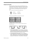
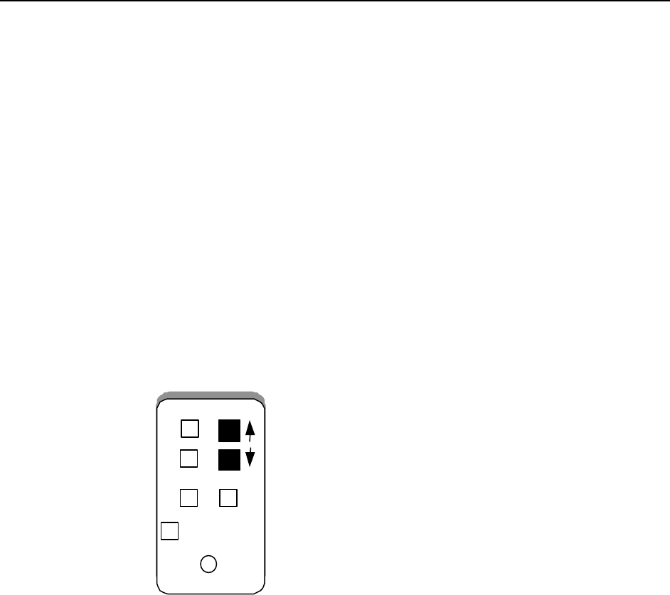
FREQUENCY
STEP
RECALL
SAVE
EXT
INPUT
50 Ohm 2 V Max
(2)
• FREQUENCY: When this key is selected (LED on), the clock up/down
keys may be used to adjust the frequency of the internal Generator clock up
or down. Each press of the frequency up or down key will increment or
decrement frequency by the current step size.
• STEP: Select this key to adjust the frequency adjustment step size from
1 kHz to 100 MHz.
• SAVE: Use this key to save the present frequency into one of 10 frequency
memory locations.
• RECALL: Use this key to recall a previously saved frequency.
• EXT: Press this key to toggle between internal clock mode (LED off) and
external clock mode (LED on).
• INPUT: This is an input for an external clock source. A signal must be
provided to this input when clock mode is set to external. However, when
clock mode is internal, any signal appearing at this input will be ignored.