


GB1400 User Manual D-1
Using GPIB, RS-232 Interfaces
This chapter describes the use of the GB1400 Bit Error Rate Tester Remote
Interfaces. Since the remote interfaces enable automatic testing, the user does
not have to complete any of the manual procedures necessary for front panel
operation. However, the user can write programs to conduct the test sessions.
Using the GPIB Interface
The GB1400 supports remote control through the GPIB interface bus connector
on the rear panel. The unit can be operated from the front panel and over the
remote interface simultaneously. All of the front panel functions can be controlled
over the GPIB interface, except `POWER.'
Remote commands sent to the GB1400 differ from front panel control. The
current operating mode is entered directly rather than through submenus.
GPIB Interface Device Settings
For proper GPIB Interface communication and handshaking, the GPIB controller
(system that controls the operation) and the device (GB1400) must have their
addresses and terminating characters set up before use.
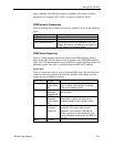
Each instrument on the GPIB interface bus needs a unique INSTRUMENT
address, programmed by 'GPIB ADDR:' key. The INSTRUMENT address range
for the GB1400 is 0 - 30 decimal. The GPIB Message Terminator is set to either
EOI or EOL/LF. For EOI, the EOI line will be asserted when the last byte of a
message is transmitted. For EOI/LF, the last byte of the message will be the line
feed character, and the EOI line will be asserted with its transmission, using
Utility menu (F1) key.
Step 1: Press the GPIB ADDR, "GPIB xx" is displayed on the LCD.
Step 2: Press the left-most UP/DOWN key (INPUT) to select the desired GPIB
address "xx".
Step 3: Press GPIB ADDR a second time.
The BERT will then respond to commands sent to that INSTRUMENT address.
This will done without affecting the remote command processing.