Specifications
A-2 GB1400 User Manual
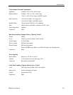
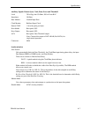
Data Patterns
Format NRZ-L, Normal and Complement
Type PRBS or WORD (User-programmable)
PRBS Patterns 2
n-1
; n=7,15,17,20,23
WORD Lengths 8 and 16-bit only,
1 Mbit memory (with optional memory)
PRBS Phase Tap Information
The Pseudo-Random data patterns used in the GB1400 TX are generated by shift-register and
exclusive-OR feedback technique. The pattern is dependent on which feedback taps (shift register
outputs) are selected.
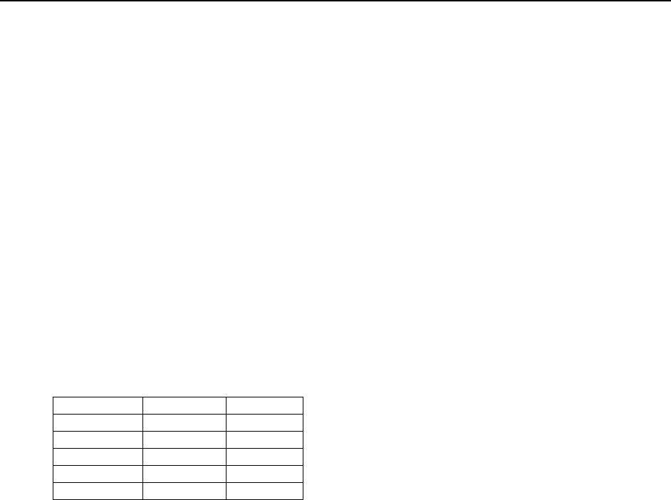
For example, PN7 is defined as a seven-stage shift register, which the output of stages 6 and 7 fed
back (through an exclusive-OR gate) to the beginning of the shift register. The feedback taps used
in the GB1400 are tabulated here.
Pattern Feedback Taps
PN7 6 7
PN15 14 15
PN17 14 17
PN20 17 20
PN23 18 23
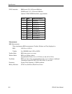
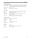
Data Output (True and Complement)
Amplitude Variable 0.5V to 2.0V, 50 mV steps
Baseline Offset Variable -2.0V to +1.0V, 50 mV steps
-2.0V to +1.8V, 50 mV steps, with PECL option
Pulse Top Limit +2.0V into 50 Ohms, +4.0V open load
+2.8V into 50 Ohms (with PECL option)
Rise/Fall Time 150 pS, typical (20-80%) at 1V amplitude
Source Impedance 50 Ohms
Output Timing CLOCK/DATA edge-aligned (+/- 100 pS)
Jitter: 100 pS, peak-to-peak Max. referenced to EXT clock
Connectors SMA
Data Inhibit Rear panel SMA, ECL (50 Ohms to -2V term)
Data Inhibit Rate Asynchronous, 1 bit and 500 pS minimum width
Data Invert Front Panel Selectable


