Using GPIB, RS-232
GB1400 User Manual D-9
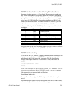
RS-232 Interface Hardware/ Handshaking Considerations
The remote interface consists of a 25-pin female D-type connector on the rear
panel. When using the RS-232C interface, connect the controller to the GB1400
with an appropriate 25-pin cable. The GB1400 is configured as an RS-232C DCE
(Data Circuit terminating Equipment). For a local (direct) connection to a DTE
device (most RS-232C controllers), connect the controller to the GB1400 with a
straight (non-null modem) cable. To connect to another DCE device, you need a
null modem to cross-connect signal pairs 2 & 3, 4 & 5, and 6 & 20.
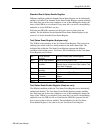
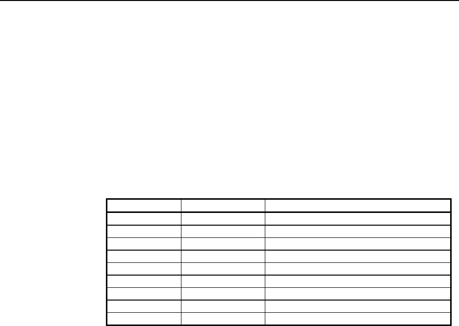
Refer to the following table for RS-232C signal names, pinouts, and functional
descriptions.
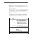
Pin Name Function
1 GND Protective Ground
2 RxD Received Data Input
3 TxD Transmitted Data Output
4 CTS Clear to Send (See note)
5 RTS Request to Send (always high)
6 DTR Data Terminal Ready (always high)
7 GND Signal Ground
20 DSR Data Set Ready
All other pins Not used
Note: Sent to the GB1400, a high-level indicates that external device is ready to
accept data from the unit. This pin must be high or open for the BERT to transmit
data. This pin is pulled high internally by 27K Ohm to +12V.
RS-232 Interface Testing
To test that the RS-232C interface is properly connected, attach a standard 25-pin
D-type connector cable between the RS-232C rear panel connector and the
controller, with the GB1400 turned off. Turn on the GB1400. The following
message should appear on the RS-232C controller’s screen, followed by the
GB1400>.
**** GB1400 RECEIVER VX.X
GB1400>
NOTE: V X.X indicates the unit's software version . The "GB1400>" line is a
prompt message indicating that the GB1400 is ready to accept a command.
If the message does not appear, check the following:
The cable may be defective.
The controller may be configured as DCE equipment. A null modem may be
needed.
The controller signal format or BAUD rate may not match the GB1400's settings.
Refer to the first part of this section for interface setting


