


GB1400 User Manual B-13
Technical note
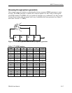
BERT - first and last measurement tool for
transmission device design acceptability
Bit error rate testers (BERTs) are the basic tool for testing the quality of transmission systems
and circuit elements. The job of the BERT is simple - to feed test patterns bit-by-bit through the
transmission path or device-under-test (DUT), and confirm that the error rate is sufficiently low.
Typical acceptable error rates might be one in one billion bits or lower.
Under the hood, BERTs are all 1s and 0s. The general-purpose BERT, one that would be used in
developing and testing serial transmission designs, independent of any communications
protocols, operates entirely on this level. You have control of the frequency (bits per second),
pattern, output amplitude and timing, and can tweak these values to stress a system to determine
the margin conditions of "acceptable" operation, and reveal design weaknesses.
Some BERTs are also designed to test quality at the data link layer of a data transmission
interface/electrical specification or protocol, beyond simply running at the correct operating
frequencies and tolerances for the standard. These BERTs are able to recognize frames/packets
and generate them, emulating the data formats called for in the standards. They are useful while
protocol standards are being hashed out. When a protocol becomes firm and established, the
BERT is replaced by the Protocol Analyzer.
The Tektronix family of BERT products (listed at the end of this article, along with specific
functionality) all conform to the above description, but differ from each other in frequency range,
number of channels, and pattern and format generation capability.
Bit error rate testing
A BERT's basic measurement is the bit error rate (BER), defined as the number of bit errors over
the total number of bits sent. This is a small, positive number, generally in the range of 10
-6
to
10
-15
. After the user connects the BERT to both ends of the transmission system or subsystem to
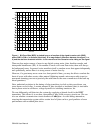
be tested, the transmitter half of the BERT sends digital test patterns across the system.
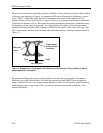
The receiver half at the other end finds the incoming signal and determines the best "decision"
voltage level and compensates for phase delay to place clock edge at the optimum point. Both
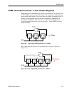
BERT Transmitter and Receiver generate the same test pattern internally using the same
algorithm, and the Receiver synchronizes its internal pattern with the pattern coming from the
Transmitter.
Simply knowing the total number of errors, however, will not help much in identifying the error
sources. Other measurements include a time dimension that can help in nailing down a source of
error. Errored seconds (ES) is the number of seconds during there was as least one bit in error.
Severely errored seconds (SES) has a BER of 10
-3
or greater. Consecutive SES is the measure of