


Application Note - Auto Search Synchronization
GB1400 User Manual 2-39
PHASE
This is a unique and very fast method of determining where the edge of a data bit
is in relation with the clock. The determination of phase errors is done by
monitoring the logic value of a data bit at the selected threshold voltage and
delay at two slightly different times. If the logic value is the same at the two
different times, then a phase error has not occurred. This method will work well
with any data that is relatively noise, jitter and glitch free.
SYNCHRONIZATION
When we state that “the receiver is synchronized”, we mean that the GB1400
Receiver’s internal reference data pattern generator is bit for bit properly aligned
with the incoming data from the device under test. When in synchronization, the
receiver can perform a bit for bit check of the incoming data against its internal
reference to determine bit errors.
DATA POLARITY
This refers to whether the device under test has inverted the data logic in relation
to what was input to it.
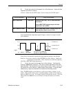
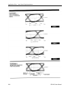
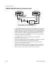
DATA EYE
This is a method of showing the data in a visual form. It is displayed on an
oscilloscope using the clock as a trigger, and the data into the vertical amplifier.
Case 1 of Diagram 1 of this application note is an example of data eye.