


Reference
3-14 GB1400 User Manual
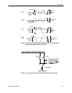
Amplitude and Baseline Offset
The rules governing the setup of clock and data amplitude and baseline offset are
as follows:
RULE 1: When terminated by 50 Ohms to ground, the amplitude adjustment
range of clock and data outputs is 0 to 2 V peak-to-peak. However, the absolute
voltage of the pulse top cannot exceed +2.0 VDC, that is:
V
amplitude p-p
+ V
offset
≤ 2.0 VDC
RULE 2: When left unterminated (termination impedance > 2 kΩ) the amplitude
adjustment range of clock and data outputs is 0 to 4 V peak-to-peak with a pulse
top limit of +4.0 VDC, that is:
V
amplitude p-p
+ V
offset
≤ 4.0 VDC
RULE 3: Displayed amplitude and baseline offset are calibrated for a
termination of 50 Ohms to ground. Any variation of termination impedance or
voltage will cause actual amplitude and offset to differ from the values shown in
the Generator display.
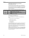
These rules are summarized in the table below.
Table 3-2. Output Setup Rules vs. Termination Impedance
Termination Amplitude Limit
(V p-p)
Pulse Top
Limit (VDC)
Actual
Amplitude
Actual Baseline Offset
(VDC)
50 Ω to ground
0 - 2 +2.0 as displayed as displayed
50 Ω to -2 VDC
0 - 2 +2.0 as displayed displayed value - 1.0 V
AC (50 Ω to AC)
0 - 2 +2.0 as displayed unspecified
Open Circuit 0 - 4 +4.0 2 x displayed as displayed
Note: With PECL option installed, the pulse top limits are increased to 2.8 (50Ω)
and +5.6 (open circuit).