


Application Note - Auto Search Synchronization
2-42 GB1400 User Manual
Auto Search will find the DATA PATTERN and POLARITY.
1. The receiver then attempts to SYNC on each data pattern and Polarity (10
possibilities). If sync is found, STOP.
2. Attempt the previous step ten times. If the pattern is not found after ten
times, go back to "Find Data V-Threshold".
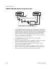
II. AUTO SEARCH Algorithm – BER Method
Like the “FAST” method of Auto Search, the “BER” method will also determine
the V-Threshold, data delay, data pattern and polarity. For this method to work,
the receiver is sensitive to the data it is analyzing and must be synchronized with
the incoming data.
This method requires the user to set criteria pertaining to Bit Error Rate threshold
and sample size that is used to determine the size and center of the data eye.
Because of the adjustability of the threshold and sample size, this method can be
made less susceptible to noise and glitches. The methods involved in analyzing
the data are quite rigorous and can require considerably more time than the
“FAST” method.
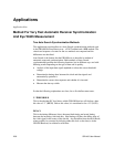
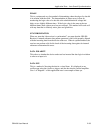
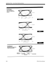
Since the GB1400 is capable of measuring and displaying "eye width", the
SAMPLE and BER THRESHOLD criteria requirements in the BER method, if
selected intelligently, tend to yield more accuracy and repeatability and is less
subject to glitches, noise, and jitter than the "FAST" method
The Auto Search BER method of determining the proper settings of the V-
Threshold, Patter, Polarity and Delay is as follows:
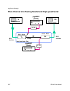
Auto Search will find the DATA V–THRESHOLD voltage.
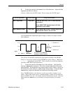
1. The receiver examines DATA ACTIVITY at each of the V – THRESHOLD
settings.
2. The receiver then locates and uses the middle of the largest voltage range
which has data activity. If no activity is detected, or if the range of activity is
less than 250 mV, then the receiver indicates “NO DATA” has been
detected.
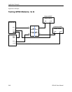
Auto Search will then attempt to find the DATA PATTERN.
This is because the data pattern needed to be able to do the BER measurements.
1. The receiver first sets the data delay to 0pS and attempts to SYNC on each
data pattern and polarity (10 possibilities). If found, go to the section
Determine Data Delay below.
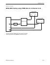
2. The receiver then sets the data delay to 1/2 of the clock period and attempts
to sync on patterns (see step 2a above). If it is found, then go to the section
Determine Data Delay below. (If the frequency is less than 250 MHz, the
receiver will use 4nS instead of the incoming clock period throughout Find
Data Pattern)