


BERT Technical Articles
B-16 GB1400 User Manual
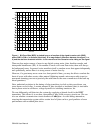
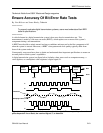
ISI errors are caused when particular patterns (symbols) of data interfere with each other, leading
to blurring and smearing of signals. An example of ISI can be illustrated by following a square
wave (1010....). When the signal leaves the transmitter, the corners of the square wave are
sharply defined. As the signal travels a couple of miles over a transmission medium, attenuation
(a function of distance) sets in. The digital waveform experiences phase delay, dependent upon
the frequency of the signal components. As a consequence, the square corners become more
rounded and blend into each other, making it difficult to tell where a pulse starts and stops. The
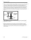
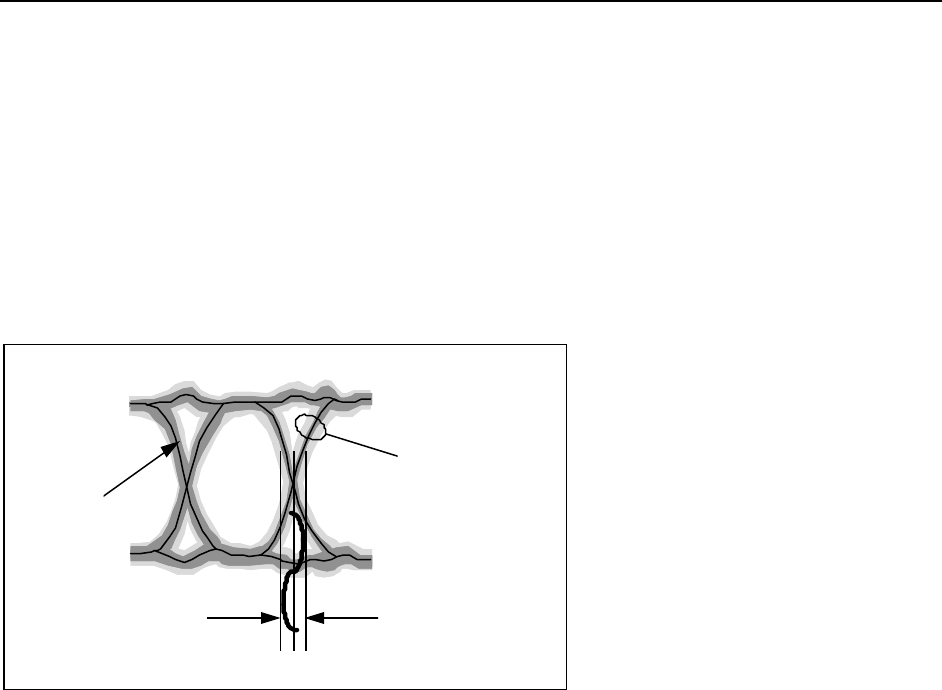
tails of data pulses interfere with following data and reduce the eye opening (example shown in
Figure 2).
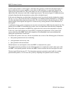
Superimposed
pulses with jitter
modulation
+ Peak- Peak
Ideal pulse
position
Jitter modulation
Figure 2. Example of a "Eye Diagram" as viewed on an oscilloscope. Pulse rounding is due to
phase dispersion, causing ISI.
By purposely adding noise, jitter or stress patterns, you can stress your design. An external
attenuator can crank a known dB of loss into the transmission path. BERTs can add jitter by
using a dithered clock so as to impair timing. Baseline wander can be tested by pattern stressing
(what happens after a long string of 0s?), causing dc drift and reducing the amplitude of the
decision threshold.