


Functional Overview
GB1400 User Manual 2-9
Outputs and Inputs
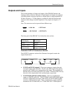
This section introduces all inputs and outputs of the GB1400 Generator and
Analyzer. Unless otherwise indicated, all signal inputs and outputs are equipped
with SMA female connectors and have a nominal input or output impedance of
50 ohms. However, a 75 Ohm Option is available for both the Generator and
Analyzer which changes nominal impedance of key inputs and outputs to 75
ohms.
Note: The same term can be expressed three different ways.
clock
= clock bar = NOT clock
DATA
= DATA BAR = NOT DATA
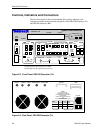
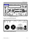
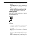
The front panel of the GB1400 Tx is divided into nine sections:
LCD Display Error Inject
Clock Pattern
Output Controls GPIB
Power Switch Output Connectors
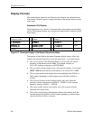
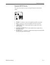
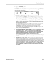
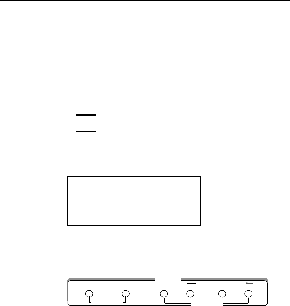
Generator OUTPUT Connectors Section
The OUTPUT connectors section of the Generator front panel contains the
outputs listed below.
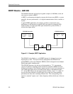
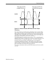
• CLOCK and DATA [outputs]: These two connectors comprise the main
test signal output of the Generator. DATA is the NRZ output of the pattern
generator and CLOCK is its corresponding clock signal. The amplitude and
baseline offset of CLOCK and DATA are variable. CLOCK and DATA may
be used to drive single-ended clock and data inputs, respectively.
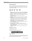
• CLOCK-BAR and DATA-BAR [outputs]: These are complimentary
outputs to CLOCK and DATA. That is, CLOCK and CLOCK-BAR together
can drive a differential clock input, while DATA and DATA-BAR together
can drive a differential data input. These complementary outputs should be
terminated with a 50 Ohm load (or a 75 Ohm load if the 75 Ohm Option is
OUTPUT
PATTERN SYNC CLOCK/4 CLOCK
CLOCK
DATA
DATA
50 Ohm SOURCE
50 Ohm SOURCE