


Functional Overview
2-6 GB1400 User Manual
Display Formats
The normal display format for the Generator and Analyzer are explained below.
Note that the "normal" format is simply the format of the display when not in the
menu mode.
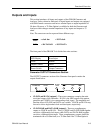
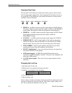
Generator (Tx) Display
The Generator has a two-line by 24-character high-contrast liquid crystal display
(LCD). The Generator display in its normal (non-menu) mode is illustrated in the
figure below.
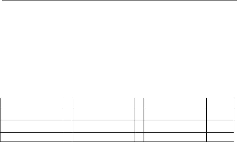
Frequency (kHz) Pattern Output
1405000 PN23 2.00 V
AMPL
FREQ 0 ERR OFF -1.00 V
OFFS
Memory
Figure 2-7. Generator Display in Its Normal (Non-menu) Mode
The function of each field in the normal Generator display format—that is the
format used when the Generator is not in the menu mode - is described below:
• The top left section of the Generator display is used to show the current
frequency of the internal clock in MHz. For example a display of
622.050 indicates a frequency of 622.050 MHz.
• The top middle section normally shows the current test pattern. For example
PN23 INV indicates that the current pattern is an inverted 2
23
-1 PRBS.
• The top right section of the display shows the amplitude of the CLOCK or
DATA output, depending on which output control (CLOCK or DATA) is
selected.
• The bottom left section of the Generator display may show either the
presently selected word memory (WORD 0 ... WORD 7) or the selected
frequency memory (FREQ 0 ... FREQ 9).
• The bottom middle section of the display shows the currently selected
Generator error inject mode.
• The bottom right section of the Generator display will normally show the
baseline offset of the CLOCK or DATA output, depending on which output
control (CLOCK or DATA) is selected.