


Functional Overview
GB1400 User Manual 2-15
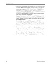
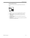
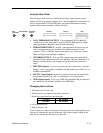
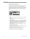
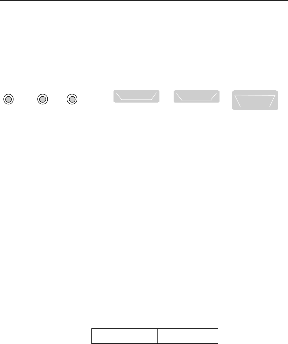
Analyzer Rear Panel
The rear-panel of the Analyzer contains the auxiliary signal, remote control,
printer, and AC-power inputs shown below. See the appendix for instruction on
how to set up the RS-232 and GPIB ports, and general information on using
printers and external controllers with the Analyzer.
PRINTER
DATA
THRESHOLD
ERROR INHIBIT RZ ERROR
OUTPUT
RS-232C GPIB
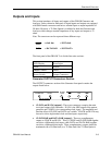
• DATA THRESHOLD OUTPUT: The programmed DATA threshold
voltage is set via the front panel. Connect to DATA BAR input for single-
ended applications. Requires external cable connection.
• ERROR INHIBIT INPUT: An ECL signal applied to this input may be
used to asynchronously gate on/off the error detection function of the
Analyzer. That is, while the signal at this input is low, errors are counted.
While it is high, error counting is inhibited.
• RZ ERROR OUTPUT: This is an ECL output signal. One pulse will be
generated at this output for each bit error detected. May be connected to an
external recording device, for example, to log the exact times that errors
occur.
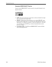
• PRINTER [output]: A one-way port that may be connected to a "parallel
printer"—that is, any printer compatible with the parallel port (LPT1 etc.) of
an IBM-compatible PC.
• RS-232-C [input/output]: A two-way serial port that may be connected to
an external controller (e.g. a PC or workstation) or to a serial printer.
• GPIB [input/output]: A two-way, IEEE-488 compatible I/O port that may
be connected to an external controller via a GPIB cable.
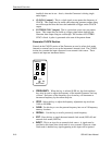
Changing the Line Fuse
1. Disconnect the AC line cord.
2. Slide the fuse cover upwards and remove the fuse.
3. Install the correct line fuse into the holder.
115 VAC 5A, Slo-Blo
230 VAC 5A, Slo-Blo
4. Close the fuse cover.
5. Plug in the line cord.
Allow at least two inches of clearance for the rear panel fan opening and at least
one inch of clearance for the top of the unit. This assures proper cooling of the
unit. Do not operate the Analyzer on its rear side.