


Getting Started
1-6 GB1400 User Manual
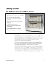
GB1400 Instrument Configurations - Standard and Burst Option
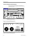
GB1400 instruments are sold with and without the BURST option. To determine if the burst option is
installed in a GB1400, press the F1 key several times until you get to the UTIL menu. Then select the
OPTION menu. The OPTIONS menu will tell you if the Burst option is installed in the unit. External
indications of the BURST option are unique labels for both transmitter and receiver. See a write-up on
Burst Mode at the end of the Functional Overview section of Chapter 2.
GB1400 with no Burst Option Standard instrument configuration
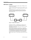
All standard configuration GB1400 Generators (no burst option) have an AC coupled external clock
input. All standard configuration GB1400 Analyzers (no burst option) have AC coupled paths in the
receiver clock input circuitry.
GB1400 with Burst Option
When the BURST option is installed in the GB1400, the AC coupled paths in both transmitter and
receiver are eliminated. This will also change several specifications listed in the table below. External
clock inputs to the GB1400 transmitter must be ECL levels when the BURST option is installed. Clock
inputs into the GB1400 receiver must be ECL levels and are terminated into 50 Ohms to -2V.
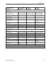
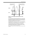
GB1400 Clock Signals for Standard and Burst and Instruments
Standard Coupling Burst (Option) Coupling
GB1400 TX
External Clock Input 50 Ohm, AC coupled,
2V max
50 Ohm to -2V, DC coupled,
ECL levels
GB1400 RX
Clock Input 50 Ohm, AC coupled,
2.0V max
50 Ohm to -2V, DC coupled,
ECL levels