


BERT Primer
GB1400 User Manual B-3
BERT Pattern Generation
Almost all BERT generators include some type of pseudo-random patterns
generation. These “PRBS” patterns are used to stimulate a “Device Under Test”
(DUT) for the purpose of comparing actual received data with the “reference”
data available to the receiver. These PRBS patterns are described below.
PRBS Patterns
A type of data pattern used by most BERTs is called “PRBS” - pseudo-random
binary sequence. PRBS patterns are categorized by the bit-length of the binary
word generating the pattern. For example, a seven-bit PRBS will be output as a
serial stream consisting of 2
7
-1 (2 to the 7
th
power minus 1 which equals 127
bits). These 127 bits include all possible permutations of seven bits with the
exception of “0000000”. Due to the nature of the Shift Register used to generate
these codes, the code 0000000 never appears. Hence the PRBS pattern is always
of the form “2
n
- 1”, e.g., 2
15
- 1, 2
23
- 1.
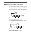
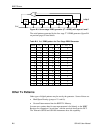
ITU Specifications (CCITT O.150 and O.151) identify several types of PRBS
patterns used for communications testing. These patterns are usually generated
by hardware shift registers with appropriate feedback. If the shift register has n-
stages, the maximum pattern length will be 2^n - 1.
If the digital signal is taken directly from the output of the shift register (non-
inverted signal), the longest string of consecutive ZERO's will equal n-1. If the
signal is inverted, n consecutive ZERO's will be produced.
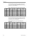
Table 1 of ITU Specification O.150 lists several different types of PRBS test
patterns. Some of the recommended test patterns use "non-inverted" signals
(PRBS 9, 11, 23), some use "inverted" signals (PRBS 15), and some use both the
"non-inverted" and the "inverted" signals (PRBS 20).