


BERT Technical Articles
B-22 GB1400 User Manual
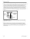
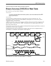
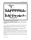
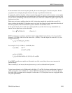
A clock source produces a clock signal, C, that times the occurrence of each bit in the digital signal. A
driver, which may be a power amplifier, a laser diode, an RF modulator, or a tape head, prepares the
signal for the system under test. The system under test can be a transmission line with repeaters, or an
optical fiber link, microwave radio link, or digital tape recorder. The received signal, F, exhibits the noise
and pulse dispersion that the transmission system adds to the digital signal.
If the noise and distortion are within limits, the decision circuit can correctly decide whether the original
bit was a 1 or a 0. The circuit does this by comparing F (at sampling instants determined by clock signal
G) with a threshold halfway between the two levels. If no errors are made in the decision process, H is a
delayed replica of the original data signal D. A clock-recovery circuit generates G from information in
data signal F.
A malfunction in any system component can cause the recovered data to differ from the original data. The
primary job of a BERT is to determine the system’s error rate rather than isolate the faulty component.
But for the sake of convenience, the BERT may replace the clock source in the transmitter or receiver.
In this case, some fault isolation may be possible by comparing the performance of the system clock
sources with that of the BERT. But for the comparison to be meaningful, users must understand the
timing jitter specifications of both units.
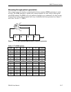
To measure the system’s error rate, the test set performs one or more of the following pairs of functions:
• data-pattern generation and error monitoring;
• clock generation and recovery; and,
• jitter generation and measurement.
Which functions are used depends on how the BERT is connected in the system.
The simplest measuring technique (see the following figure) is to replace the system’s data source with
the BERT’s data-pattern generator and have the BERT receiver monitor the recovered signal for errors.
The data signal D then becomes D′. The data-pattern generator can mimic typical traffic by creating
pseudorandom patterns, or it can stress the system by outputting fixed patterns stored in memory.