


Theory of Operation
I-4 GB1400 User Manual
In PRBS mode, the Pattern Sync circuit detects the start (n, 1, zeros) of the PRBS
pattern. This produces a single bit width pulse once per pattern frame. In WORD
mode, the shift register detects the programmable WORD load pulse, which
occurs once per WORD frame.
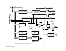
Error Counter PCB
The Error Counter PCB contains the circuitry to count the Bit Errors detected by
the Data Generator PCB, and also measures the system clock frequency. A Bit
Error Rate (BER) is defined as a ratio of errors/bits, the CPU divides the total
errors by the total bits, and displays the quotient on the front panel LCD as BER.
Total bit errors are also displayed, along with frequency. All counting is done at
full rate, latched and calculated by the CPU.
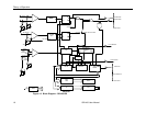
Common to both GB1400 TX and GB1400 RX
CPU PCB
The CPU PCB contains the CPU, RAM and software PROMs. The 80188
microprocessor handles all inter-board communication, storage and loading of
the programmable 16-bit WORD error counting and frequency calculations,
internal clock PLL control and scale calculations, front panel interface and
remote communication over the RS-232C and GPIB interfaces. Battery-backup
RAM provides storage of ten programmed data patterns, ten programmed clock
frequencies error status, and unit operating status after power loss.
Front Panel PCB
The front panel PCB provides user control of the unit, and contains the key
decoders, LED drivers and 2 x 24 liquid crystal display.