


Index
Index-2 GB1400 User Manual
-C-
Controls, Indicators, and Connectors, 2-4
Controls & Indicators, 2-18
Analyzer ERROR DETECTION, 2-25
Analyzer Error History, 2-24
Analyzer INPUT, 2-23
Analyzer SYNC Controls, 2-25
Func (Soft) Keys (F1, F2, F3, F4), 2-21
Generator ERROR INJECT, 2-22
GPIB Controls, 2-19
Pattern Controls, Function Keys, 2-20
Power Switches, 2-18
Reset to Factory Default, 2-18
Unit Cooling , 2-18
Unit Mounting , 2-18
View Angle and Panel Lock Keys, 2-18
-D-
Display Formats, 2-6
-F-
Figures
Analyzer (RX) Front & Rear Panels, 2-5
Analyzer Clock and Data Input
Equivalent Circuits, 3-22
Analyzer Display, 2-7
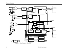
Block Diagram - GB1400 RX, I-6
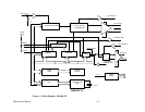
Block Diagram - GB1400 TX, I-5
Example of BERT Application, 2-2
Four-stage PRBS generator, B-5
Generator Front & Rear Panels, 2-4
Generator Clock and Data Output
Equivalent Circuits, 3-17
Generator Display, 2-6
Nominal Generator Clock, Data
Waveforms showing Amplitude,
Baseline Offset and Vtop, 3-13
Nominal Generator NRZ Data and
Clock Output Waveforms, 2-3
Seven-stage PRBS generator, B-6
TEST Measurement Process, 3-32
Three-stage PRBS generator, B-5
TOTALIZE Measurement Process, 3-30
WINDOW Measurements Process, 3-31
Functional Overview, 2-1
Functions common to TX and RX, 3-1
AC Power, 3-1
LCD Viewing Angle, 3-1
Locking the Front Panel, 3-2
Recalling Default Setup, 3-2
Selecting 115 VAC or 230 VAC
operation, 3-1
Turning Instrument Power ON/OFF, 3-1
-G-
Generator Functions, 3-10
Amplitude and Baseline Offset, 3-14
Clock Source and Frequency, 3-10
Clock Source, 3-10
Data and Clock Outputs, 3-12
Error INJECT Input, 3-18
Error Injection, 3-17
External Clock Input, 3-10
Logically Inverting Output Data
(D-INV), 3-15
Pattern SYNC (PYNC) and CLOCK/4
Outputs, 3-16
Recalling a Frequency, 3-11
Saving a Frequency, 3-11
Selection an Error Inject Mode, 3-17