


Functional Overview
GB1400 User Manual 2-13
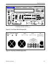
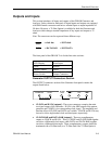
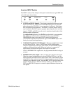
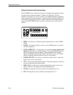
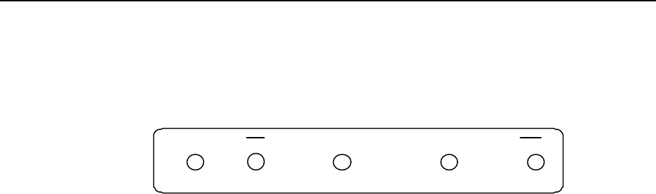
Analyzer INPUT Section
The INPUT section of the Analyzer front panel contains the test signal NRZ data
and clock inputs shown below.
REFERENCE DATA CLOCK
CLOCK
DATA
DATA
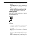
• CLOCK and DATA [inputs]: These inputs comprise the main test signal
input to the Analyzer. DATA is the main NRZ data input to the Analyzer
pattern detector and CLOCK is its corresponding clock signal. Both inputs
have selectable input terminations. In addition, a variable amount of delay
may be added to the DATA input to properly phase-align the clock and data
signals. CLOCK and DATA may be used to terminate singled-ended clock
and data outputs, respectively.
For single-ended applications, the DATA input threshold is programmable.
This requires an external cable connection from the rear panel DATA
THRESHOLD output to the unused DATA input. Only the unused
"DATA-BAR" input needs the threshold signal. The CLOCK input is self-
biasing for single-ended applications.
• CLOCK-BAR and DATA-BAR [inputs]: These are complimentary inputs
to CLOCK and DATA. That is, CLOCK and CLOCK-BAR together
comprise a differential clock input, while DATA and DATA-BAR together
comprise a differential data input. When the Analyzer is connected to
singled-ended clock and data signals, these inputs are not used.
Note: In DIFFERENTIAL applications, the programmed threshold voltage is
not used.
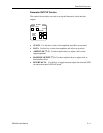
• REFERENCE DATA [input]: This is an input for a reference data signal.
When the external reference mode is selected (LED in EXT key is on), the
signal appearing at the REF DATA input will be used as the reference signal
to perform bit error analysis instead of a (reference) pattern generated by the
Analyzer's error detection circuit. Note that REF DATA uses the same clock
signal as DATA, however different amounts of delay can be added to the
DATA and REF DATA inputs to account for phase differences between the
two signals.