


Reference
GB1400 User Manual 3-17
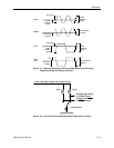
Error Injection
The GB1400 Generator can inject bit errors, also known as logic errors, into the
output data pattern. One use of error generation is to self-test the GB1400
Generator/Analyzer system. Or, when generating WORD patterns containing
simulated framed signals, for example a SONET signal, error generation can be
used to determine the ability of the terminal under test to detect errors or to stay
in-frame in the presence of high error rates.
The available internal error injection rates are 10
-n
, where n = 7, 6, 5, 4, or 3. In
other WORDs, injected BER can be set to integer powers of 10 from 10
-7
to
10
-3
. Using the external error inject mode, errors can be injected at any rate up to
10
-3
. There is no lower limit on external error injection BER.
Selecting an Error Inject Mode
The controls that determine the error injection mode of the Generator are:
RATE (key)
SINGLE (key)
When the LED on the RATE key is off, the Generator is in the single error inject
mode. In this mode, no errors are generated except when the SINGLE error key
is pressed. That is, each press of the SINGLE key will cause a single, isolated bit
error to be injected. However, when the RATE key is on, the instrument is either
generating an error rate internally, or under external error generation control.
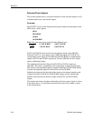
You can determine which by observing the bottom, middle field of the display.
If an error rate is displayed (e.g. ERR 1E-09) then the Generator is in the internal
error inject mode. If the message EXT ERR is displayed, then the external error
inject mode has been selected indicating that the signal appearing at the rear-
panel EXTERNAL ERROR INJECT input will control error injection rate. One
error will be generated for each negative-to-positive transition in this signal. In
all other error inject modes, the signal appearing at this input will be ignored.
NOTE: In all error injection modes, the ERROR LED will flash each time an
error is injected.