


Specifications
GB1400 User Manual A-7
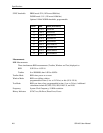
Auxiliary Signals: Pattern Sync, Clock, Data, Error and Threshold
Level 250 mVp-p into 50 Ohms, 500 mV into Hi-Z
Impedance 50 Ohms
Data Monitor Latched Input Data
Clock Monitor Buffered Input Clock
Pattern SYNC 1-bit wide pulse per frame
Error Inhibit Rear panel, ECL
Error Output Rear panel, ECL
AUX Rear panel, Data Threshold output
Note: Connect this output to DATA BAR (Not DATA) for
single-ended operation.
Connectors SMA
Synchronization
Auto Search
Unit automatically finds the Data Threshold , the Clock/Data input timing phase delay, the input
Data Pattern (PRBS or WORD mode), and Data Polarity.
There are two modes to find the Data Delay
FAST - A quick method using the Clock/Data phase indicator.
BER - A slower method which uses the signal's bit error rate.
Either method will make available the width of the Data Eye (if possible). The BER method
allows user control over:
Data Sample Size (10E-4 to 10E-11). This is the number of data bits sampled at each Delay
setting used to determine the center of the Data Eye.
Bit Error Rate Threshold (10E-3 to 10E-10). This is the threshold used to determine which Delay
settings are part of the Data Eye Crossing.
Manual Mode
User selects parameters, then unit attempts to synchronize on the input data pattern.
Disable Mode SYNC circuitry disabled