


BERT Technical Articles
GB1400 User Manual B-29
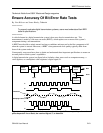
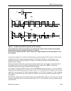
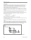
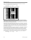
If the transmitter clock source has phase jitter θ
i
, the received data signal, F, has the same jitter. But the
eye pattern does not display this jitter because the scope is synchronized to the data.
In general, θ
o
, which is the phase of the recovered clock signal, G, cannot track θ
i
, exactly, so some phase
error (θ
e
=θ
i
-θ
o
) exists between the clock and the data. With the oscilloscope synchronized to the data, this
error is seen as a broadening of the recovered clock’s trace. The trace’s width is the peak-to-peak value of
the phase error jitter.
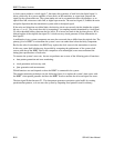
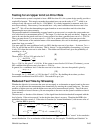
Phase error can cause a problem when the clock’s rising edge samples the received data to see if it is
above or below the threshold. If the phase error is too great, the rising clock edge approaches the sides of
the data eye pattern, and the transmission system’s decision circuit makes errors.
If the spectral density of the clock-source phase jitter Φ
θi
(f) and the clock recovery bandwidth f
B
are
known, the rms phase error can be calculated:
θ
erms
= (π/2)f
B
Φ
θi
(f
B
) (Equation 1)
BERT manufacturers sometimes specify the clock’s single-sideband noise density, Φ
vi
(f), at an offset
frequency of 10 kHz, which is also the value of Φ
vi
(10 kHz). From this figure, the value of F
qi
(f
B
) can
be approximated by:
F
qi
(f
B
)=(10 kHz/f
B
)
2
F
qi
(10 kHz).
For example, if F
vi
(f
c
+10 kHz) is -84dBc/Hz, then:
F
qi
(10 kHz) =10
-84/10
=2.5×10
-9
rad
2
/Hz
and for f
B
=16 kHz,
F
qi
(f
B
)=(10 kHz/16 kHz)
2
×(2.5×10-9)=10
-9
rad
2
/Hz.
If the BERT manufacturer supplies no information on clock-source jitter, the user must measure the
spectral density.
Once f
B
and Φ
qi
(f
B
) are known, the rms phase error q
erms
can be calculated from Equation 1.
Typical spectral density at f
c
=70 Mhz and f
B
=16 kHz is 10
-9
rad
2
/Hz. For these specifications, Equation 1
yields an rms phase error of 0.005 rad, or about 0.0008 UI (unit intervals), where 1 UI=2π rad. Because
the width of the eye pattern in this example is on the order o f1 UI, the phase error has a negligible effect
on system performance.