BERT Technical Articles
GB1400 User Manual B-31
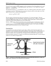
A BERT designed to measure jitter has a phase demodulator connected to the covered clock. The range of
f
m
is from f
1
=10 Hz to f
4
; the amplitude depends on f
m.
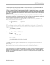
The BERT’s jitter generation and jitter measurements specifications should be somewhat higher than the
maximum jitter that a system can typically tolerate. As a result, a BERT with jitter generation can find a
receiver’s θ
e max
by setting f
m
=f
4
and increasing A until the receiver begins to make errors. In addition, the
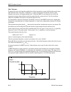
clock-recovery bandwidth, f
B
, can be estimated by lowering f
m
until the jitter tolerance begins to exceed
θ
e max.
BERT Affects Accuracy
Several BERT characteristics can affect the accuracy of system measurements. For instance, a BERT
transmitter may have a very jittery clock source, such as an open-loop voltage-controlled oscillator. If so,
the system will have a higher error rate or less margin than when the system’s clock source is used.
Measuring the clock-source spectral density and calculation θ
e rms
will uncover this problem.
Another snag may be that a BERT receiver has a very narrowband clock-recovery circuit, such as crystal
controlled phase locked loop. The small f
B
will probably make the BERT less tolerant of jitter than the
system its testing. In high jitter situations, therefore, the BERT will report a higher bit error rate than the
actual rate. A BERT transmitter with jitter generation can measure its own receiver’s jitter tolerance and
that of the system to see which is greater.
The question of whether a BERT data pattern fairly represents live traffic is more difficult to answer.
Experience indicates that long PRBS patterns (N greater than 14 ) stress the system more than most live
traffic does. But it is rare traffic with unusually stressing patterns that is most interesting. Therefore, the
best users can do is to anticipate these patterns and generate them with fixed patterns from the BERT
transmitter.
============


