


Performance Verification
GB1400 Acceptance Test E-3
Functional Test
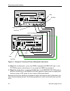
To functionally test the GB1400, connect the Generator to the Analyzer and confirm
their correct operation as described below.
Note
In these procedures, the Generator and Analyzer are returned to their default
settings. The word memories will be reset. If you have entered word patterns
that you do not want to lose, use a GPIB or RS-232C controller to save them
before beginning these procedures.
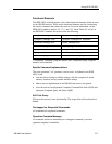
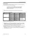
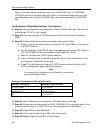
q Step 1: Make connections appropriate to the options installed as follows:
Connections for Functional Test
Option From To Comment
Standard Instrument TX Clock RX Clock 50 Ohm, SMA coax
TX Not Clock RX Not Clock 50 Ohm, SMA coax
TX Data RX Data 50 Ohm, SMA coax
TX Not Data RX Not Data 50 Ohm, SMA coax
75 Ohm Option TX Clock RX Clock
TX Not Clock RX Not Clock
TX Data RX Data
TX Not Data RX Not Data
50 Ohm, SMA coax.
Use SMA to BNC
adapters and 75 Ohm
BNC coaxial cables
See Figure 1 for Setup of Functional Test.
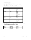
q Step 2: Reset both the Generator and Analyzer to their factory default settings.
Press the ‘CLEAR’ key in the PATTERN section, the ‘MSB(1)’ key and the ‘VIEW
ANGLE’ key, and hold down all three keys while cycling the power.
The message DEFAULT SETTINGS should appear briefly on the display of each unit,
followed by the GB1400 logo, before the functional display appears.
q Step 3: At the Generator, verify that error injection is off (you should see ERR OFF
on the display). If error injection is on, press the ‘SINGLE’ key in the ERROR
INJECT section to turn it off.