


BERT Technical Articles
GB1400 User Manual B-25
D’
1
-1
Avergage = -0.5 Average = 0.5
Pattern A Pattern B Pattern A
Time
1
F
2
1
-1
0.5
RC 0.5
Time
(b)
(c)
R 50
(a)
D’
C
0.1 Fµµ
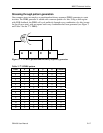
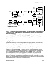
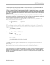
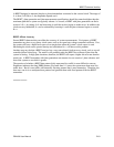
Figure 3. (a) Most transmission systems use AC coupling.
(b) Consequently, a bit-error-rate tester can measure the system's noise margin by generating
signal patterns with an unbalanced number of 1s and 0s.
(c) The result is baseline wander, which reduces the margin between the received signal, F, and
the threshold.
As long as the number of 1s and 0s in the data pattern is equal, the pattern’s DC content is fixed, and the
coupling circuit doesn’t block anything important. If the balance changes at a low frequency, the
coupling circuit may block that frequency, causing F to wander up and down. This baseline wander
reduces the noise margin.
Properly designed transmission systems ensure that data patterns have no frequency components below
the coupling circuit’s cutoff, essentially eliminating baseline wander. But a BERT can purposely
introduce some baseline wander to measure the noise margin.
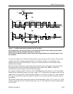
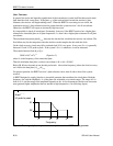
An example is an input signal D’ that starts with a 10001000 pattern and switches to a 11101110 pattern.
During the first imbalanced pattern, the average voltage, -0.5 V is blocked by the coupling circuit, and the
output F has an average of 0 V. When the pattern changes to 11101110, D′ averages 0.5 . After a transient
with a time constant of RC=5µs, the average of F returns to zero, and the signal has wandered by half of
its amplitude.
This baseline wander reduces the margin between F and the threshold by 50%, to 0.5 V from 1.0 V. If this
reduction caused the error rate to become measurable--say 10
-6
--the conclusion is that the original margin
was about 50%.