


Functional Overview
GB1400 User Manual 2-21
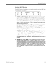
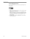
Function (Soft) Keys (F1, F2, F3, and F4)
Menu Functions: The primary use of the function keys in the Generator and
Analyzer is to access and navigate each instrument's menu system. F1 may be
thought of as the main menu key. Pressing F1 will display the instrument's first
level menu. Once inside the menu system, you may use the F1, F2, F3, and F4
keys to select different menus, or to make choices within a selected menu. Note
that pressing the F1 key enough times will always get you out of the system. See
Chapter 3 - Reference for an explanation of each Generator and Analyzer menu.
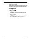
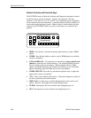
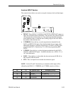
Analyzer Inputs
These function keys provide signal inputs and control of parameters (Input
Termination, Threshold, Logic Polarity and Data/Clock Phase Delay) for DATA,
Ref DATA, and CLOCK.
Selecting DELAY, V-TERM or V-THRS permits the INPUT Up/Down keys to
vary the Input parameters for DATA, as described below. Holding the Up/Down
key repeats the function five times a second.
Function key F2 (CLOCK) permits the V-TERM key to vary only the Input
termination parameters for CLOCK.
Function key F3 (Ref DATA) permits the DELAY, V-THRS, and V-TERM keys
to vary the Input parameters for Reference DATA.
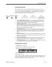
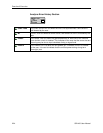
DELAY - Pressing DELAY selects Input Data Delay adjust mode. The Input
Data signal can be delayed over the range 0.0 nS to 3.9 nS in sub-nanosecond
steps. The delay is modified with the INPUT Up/Down keys. The current Delay
is displayed on the lower left side of the LCD.
An illuminated Delay LED light indicates that the unit's DELAY can be modified
by the Up/Down arrow keys.
V-TERM - Pressing V-TERM selects V-termination mode. The input
termination voltage for Input Data is selectable between GND, -2.0V, and AC.
-2.0V mode provides active termination for ECL and GaAs signals. AC mode
allows RF termination.
An illuminated V-TERM LED light indicates that the input termination can be
modified by the Up/Down arrow keys.
V-THRS - Pressing V-THRS selects V-Threshold mode. The Input Data
threshold is variable over the range of -1.5V to +1V in 50 mV steps. The
currently selected threshold voltage is displayed in the lower right side of the
LCD display.
An illuminated V-THRS LED light indicates that the threshold voltage can be
modified by the Up/Down arrow keys.
The Data threshold voltage is available at the Analyzer rear panel SMA jack
labeled DATA THRESHOLD.
Print Setup Function (Analyzer only): You can print a report showing the
current setup of the Analyzer by pressing the F4 key. This function, however, is
not active in the menu mode.