


BERT Technical Articles
B-18 GB1400 User Manual
PRBS generators are named after the number of combinations they generate; thus the 2
8
-1 PRBS
is generated from 255 unique 8-bit combinations, each producing one bit in the output stream.
The all-zero state is excluded (accounting for the -1 in 2
8
-1", above), because it would generate
itself and no other combination.
The purpose of a PRBS is to stress a system by testing possible combinations of data that could
pass through the device, bringing out different types of problems. PRBSs have predictable
patterns, consisting of strings of 1s and 0s.
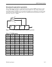
For example, the 8th through the 11th bits of the 2
4
-1 PRBS are all 1s (see Table 2), followed by
three 0s. If we were looking at a 2
31
-1 PRBS, at some point, we would set thirty-one 1s and later
thirty 0s would cycle through the system. Such a sequence of patterns could cause the data
baseline to wander.
Depending on your application, PRBSs may not simulate the kind of traffic you expect to see
across your lines. Again, the goal of the PRBS is to stress your system in ways that help you to
understand its limits and the quality you can expect from it under ordinary circumstances. Note
that the shorter PRBSs are quicker to repeat: a 2
8
-1 PRBS repeats every 255 bits, whereas a 2
31
-1
PRBS repeats every 2,147,483,647 bits.
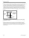
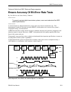
ITU Specifications (O.150 and O.151) identify several types of PRBS patterns used for
communications testing. These patterns are usually generated by hardware shift registers with
appropriate feedback. If the shift register has n-stages, the maximum pattern length will be
2^n - 1.
If the digital signal is taken directly from the output of the shift register (non-inverted signal), the
longest string of consecutive ZEROs will equal n-1. If the signal is inverted, n consecutive
ZEROs will be produced.
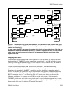
The ITU Specification O.150 lists several different types of PRBS test patterns. Some of the
recommended test patterns use "non-inverted" signals (PRBS 9, 11, 23), some use "inverted"
signals (PRBS 15), and some use both the "non-inverted" and the "inverted" signals (PRBS 20).
Tektronix GB700/ GB1400 BERTs provide the ability to invert data on both transmit and
receive. This provides full flexibility to adjust the PRBS signal to the user's exact requirements.
A cousin of the PRBS is the quasirandom signal source (QRSS). QRSS patterns constrain the
number of 0s that can appear within a sequence (for example, a 2
20
-1 pattern with no more than
fourteen 0s within each 20-bit combination). QRSS patterns can also be named n:x, short for
n-in-x (for example, the 3:24 QRSS cycles through all combinations that contain three 1s and
twenty-one 0s).
Other pattern generating options might include all 1s (1111...), all 0s (000...), or alternating 1s
and 0s (1010...), or mark density. In general, cycling through several different patterns tends to
stress a system more than continuously running a single pattern.
Most BERTs have internal memory to allow the creation and storing of your own test patterns.
These patterns may be real traffic, combinations that stress particular aspects of your design, or
data with intentional errors. Some BERTs allow you to mix saved patterns and generated
patterns.