


Theory of Operation
GB1400 User Manual I-3
GB1400 Analyzer (RX)
Design Overview
The GB1400 RX is designed to receive a differential or single-ended
programmable WORD of 16-bits, and five PRBS of 2
n-1
(n=7, 15, 17, 20, 23), at
serial data rates of up to 1400 Mb/s, compare it to a locally-generated identical
data stream and perform Bit Error Rate (BER) analysis upon it.
Very high frequency GaAs, ECL and discrete circuitry is incorporated on
multilayer controlled impedance pretend circuit boards. RF shielding and
critically timed coaxial cables provide wideband operation with sub-nanosecond
timing. An embedded CPU controls the high-speed data generator hardware,
programmable WORD loading, error counter calculations, AUTO SEARCH
parameters, remote RS-232C and GPIB interfaces, and soft front panel control.
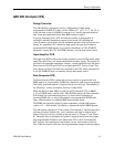
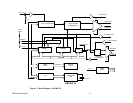
Input Amplifier PCB
The Input Amp PCB contains the circuitry required to receive differential/ single-
ended Data and Clock, and single-ended Reference Data signals. The signals are
provided with selectable termination voltages, variable threshold level and phase
delay between CLOCK and DATA to accommodate DUT (Device-Under-Test)
skew. Delay and Input Threshold are controlled by the CPU either automatically
in AUTO SEARCH mode, or manually through front panel control.
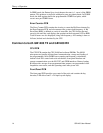
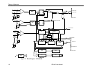
Data Generator PCB
The Data Generator PCB contains the circuitry required to generate the local
PRBS pattern or programmable WORD for comparison with the received pattern.
The locally-generated pattern is compared bit-by-bit at full rate. The differences
are "Bit Errors" and are counted by the Error Counter PCB.
When the Bit Error Rate (BER) exceeds the SYNC threshold (25% in PRBS,
3.1% in WORD mode, variable with 1 Mbit WORD option), the Data Generator
PCB initiates the synchronization process, by feed-forward technique on
incoming PRBS data, or clock-slip technique on programmable WORD data.
Once synchronization is established BER measurements begin.
The PRBS data generator utilizes a pattern dependent, n-length shift register
(where of 2
n-1
) with modulo-2 feedback, to generate the desired PRBS pattern.
The shift register operates at 1/2 the system clock frequency. The half-rate data is
split into two phase shifted rails - one is reference, the other is delayed half a
frame. These two rails are available at the rear panel, as "Phase A", and "Phase
B". Internally they are multiplexed together to generate the full rate data output.
The programmable WORD is level shifted from TTL to ECL and loaded into
ECL registers, then multiplexed and clocked out in a serial stream at full-rate.
The 16-bits are loaded at full rate, allowing immediate change to the data pattern.