


Functional Overview
2-16 GB1400 User Manual
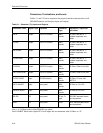
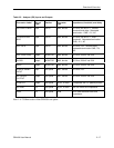
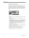
Connectors, Terminations, and Levels
Tables 2-1 and 2-2 below summarize the physical interface characteristics of all
GB1400 Generator and Analyzer inputs and outputs.
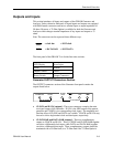
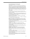
Table 2-1. Generator (Tx) Inputs and Outputs
Connector Label Signal Type Location Connector
Type
Impedance, amplitude,
and offset
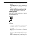
DATA output OUTPUT section SMA,
female
50 Ohm, see NOTE 1,
variable amplitude and
offset
CLOCK output OUTPUT section SMA,
female
50 Ohm, see NOTE 1,
variable amplitude and
offset
DATA-BAR output OUTPUT section SMA,
female
50 Ohm, see NOTE 1,
variable amplitude and
offset
CLOCK-BAR output OUTPUT section SMA,
female
50 Ohm, see NOTE 1,
variable amplitude and
offset
CLOCK/4 output OUTPUT section SMA,
female
50 Ohm, 200mV into 50Ω
PATTERN SYNC output OUTPUT section SMA,
female
50 Ohm, 200mV into 50Ω
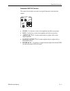
CLOCK INPUT input CLOCK section SMA,
female
50 Ohm, 2V max, see
NOTE 2
DATA INHIBIT input rear panel BNC,
female
50 Ohm to -2V, ECL
ERROR INJECT input rear panel BNC,
female
50 Ohm to -2V, ECL
RS-232 I/O rear panel 25 pin, D
type
RS-232C standard levels
and impedance
GPIB I/O rear panel GPIB IEEE-488 standard levels
and impedance
Note 1: A 75-Ohm version of the GB1400 is an option.
Note2: BURST Mode units require ECL-level inputs and are terminated with 50-Ohms to -2V.