


Reference
3-18 GB1400 User Manual
Procedure to Control Error Injection Mode
1. Press the RATE key one or more times to select the desired error injection
mode. Note that the LED in the RATE key will turn on except when mode is
set to ERR OFF. Available selections are:
ERR OFF: Single error injection.
ERR 1E
-7
: Generate errors at rate of 10
-7
.
ERR 1E
-6
: Generate errors at rate of 10
-6
.
ERR 1E
-5
: Generate errors at rate of 10
-5
.
ERR 1E
-4
: Generate errors at rate of 10
-4
.
ERR 1E
-3
: Generate errors at rate of 10
-3
.
ERR EXT: External error inject mode.
2. Once you have selected an internal error rate, or the external mode, you can
turn this error rate off and on by alternately pressing the SINGLE key and
RATE key. Do not press the RATE key two or more times in a row unless
you want to change the current error injection mode. However, while the
current error rate is off, you can press the SINGLE key as many times as you
wish to inject single errors.
3. To return to the single injection mode, press RATE one or more times until
ERR OFF is selected.
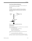
ERROR INJECT Input
The ERROR INJECT input is an SMA (female) connector located on the rear-
panel of the Generator. When the error injection mode is set to ERR EXT, one bit
error will be generated for each rising edge in the signal applied to this input.
Setup - The ERROR INJECT is a 50 Ohm, ECL input. No hardware setup is
required.
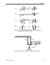
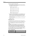
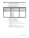
Data Inhibit - The DATA INHIBIT input is located on the rear-panel of the
Analyzer. A signal applied to this input may be used to gate off and on the
Generator DATA output signal. The logic of the DATA INHIBIT function is
shown in the following table. The DATA INHIBIT function is not bit or frame
synchronized with the DATA output signal. Therefore, the gating action caused
by the DATA INHIBIT input may occur anywhere within a DATA output bit
time slot and anywhere within a pattern frame. DATA INHIBIT is a standard 50
Ohm ECL input and does not require any threshold or delay setup.
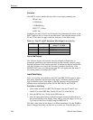
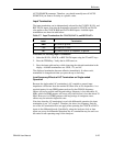
Table 3-3. Data Inhibit Logic
Logic Level Applied to
DATA INHIBIT INPUT
Action
OPEN or LOW DATA output operates normally.
HIGH DATA output is disabled, that is forced LOW.