


A-2
1.3 Names and functions
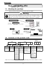
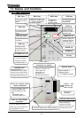
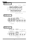
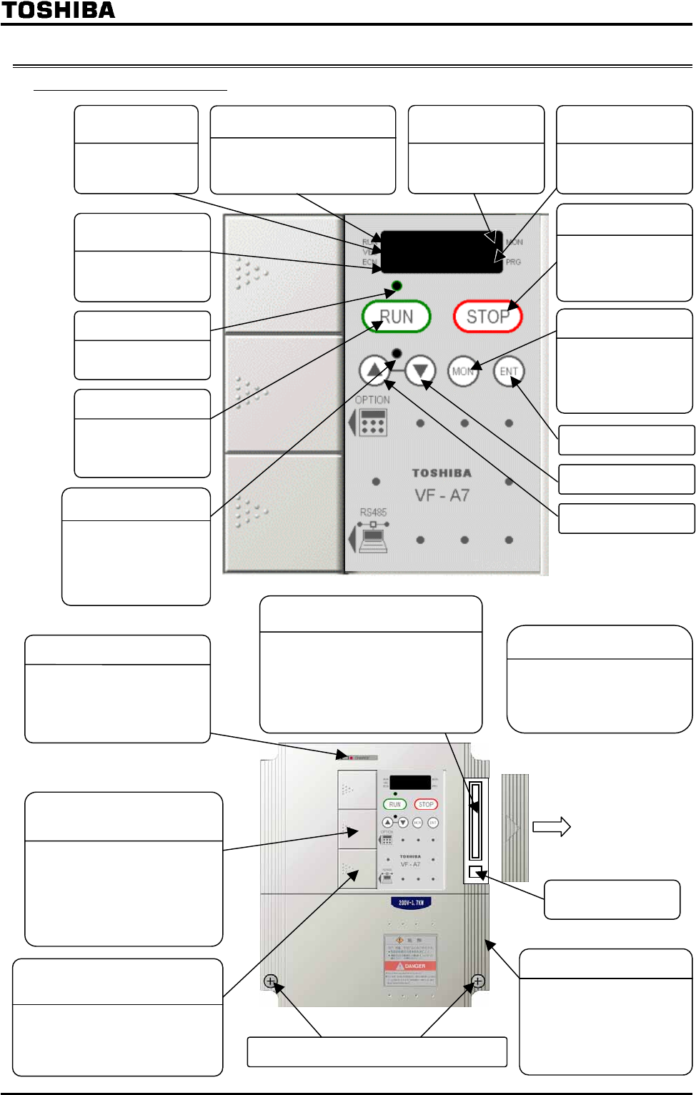
1.3.1 Panel description
[ Front view ]
To use connectors reserved
for options, detach this
cover by sliding it to the
right.
Parameter writer
Extension panel, etc.
Cover for common serial
option connectors
To use an RS485 connector,
detach this cover by sliding it to
the right.(Refer to 2.3.3)
Cover for serial RS485
connectors
Used to install the following options:
Expansion TB option unit
Vector option unit
F10M option unit
S20 option unit
PG feed back board, etc.
Connector for options
Sink/source
switching
CHARGE lamp
Indicates that a high voltage
remains in the inverter. Do not
open the terminal board cover
for safety while this lamp is lit.
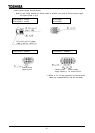
Be sure to attach the cove
r
before starting the
operation to prevent
persons from touching the
terminal board in error.
Terminal board cover
Terminal board cover fixing screws
RUN key lamp
Lit when the RUN key
is enabled.
RUN key
Pressing this key
while the RUN key is
lit starts the motor.
STOP key
Pressing this key
while the RUN key
lump is lit causes
the motor to make a
slowdown stop.
UP/DOWN key lam
With these keys, you
can set the operation
frequency while the
UP/DOWN lamp is lit.
VEC lamp
Lit when the Inverter
is in vector control
mode.
UP key
DOWN key
RUN lamp
Lit when the inverter is in
operation or blinks when It
is in auto acceleration/
deceleration mode.
MONITOR key
MON lamp
Lit when the
inverter is in
monitor mode.
PRG lamp
Lit when the inverter
is in parameter
setting mode.
ENTER key
ECN lamp
Lit when the inverter
is in energy-saving
mode.
Used to display the
operation frequency,
parameter setting
error messages, etc.
Optional board
Used to install the
following options:
PG feedback options
Pushing mark,
make this cover
slide to the right.