


G-8
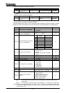
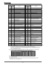
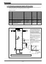
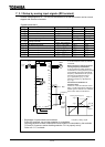
Parameter setting
Positive
logic
Negative
logic
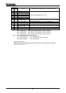
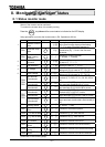
Function Operation output specifications (in case of positive logic)
92 93
Designated data output #1
94 95
Designated data output #2
96 97
Designated data output #3
98 99
Designated data output #4
100 101
Designated data output #5
102 103
Designated data output #6
104 105
Designated data output #7
Output of the designated data in 7 bits.
106 107 Light load signal
"ON": Load is equal to (Heavy load torque) set
values or less.
108 109 Heavy load signal "ON": Load is larger than set value.
110 111 Positive torque limit "ON": Positive torque is over the positive torque limit level.
112 113 Negative torque limit "ON": Negative torque is over the negative torque limit level.
114 115
Output for external rush
suppression relay
"ON": External rush suppression relay is actuated.
116 117 Over travel "ON": Over running
118 119
Completion of positioning
"ON": Positioning has been completed.
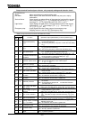
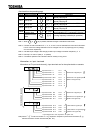
Note 1: "ON" in positive logic: Open collector output transistor or relay is turned on.
"OFF" in positive logic: Open collector output transistor or relay is turned off.
"ON" in negative logic: Open collector output transistor or relay is turned off.
"OFF" in negative logic: Open collector output transistor or relay is turned on.
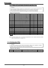
Note 2: Alarm output check conditions are as follows.
1) Under-voltage detected: To be checked always.
2) Low current detected: To be checked during operation command.
3) Over-torque detected: To be checked always.
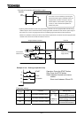
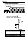
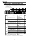
Sink logic/source logic
Sink logic and source logic (input/output terminal logic) can be switched to each other.
Refer to the section 2.3.2