


G-3
Inverter
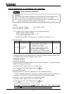
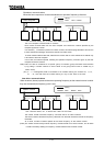
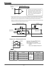
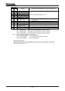
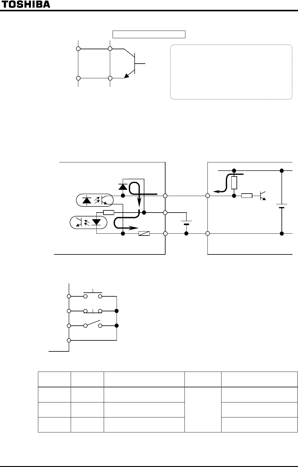
3) In case of connection with transistor output
Regarding interface between inverter and programmable controller In the case programmable controller of open
collector output is used to control the inverter, if the programmable controller is turned off as the power supply to
the inverter is on, such a wrong signal as shown in the following figure flows into the inverter because of
difference in potential of control power. Be sure to provide the system with an interlock so that the programmable
controller cannot be turned off while the inverter is turned on.
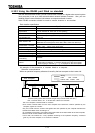
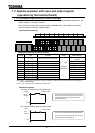
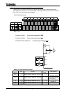
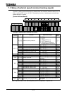
Example of use - Push-type operation stop
Operation: Press the START button.
Stop: Press the STOP button.
Switch between forward and reverse
rotation:
Short circuit between S2 and CC.
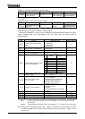
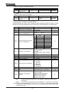
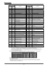
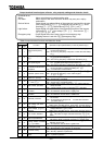
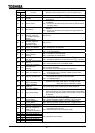
[Parameter setting]
Symbol of
terminal
Title Function
Adjustment
range
Setting value
F
Input terminal selection #1(F)
(PUSH-type run command)
S1
Input terminal selection #5(S1)
(PUSH-type stop command)
S2
Input terminal selection #6(S2)
(Refer to
page G-4)
(Forward/reverse selection)
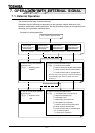
The inverter can be controlled by connecting the
input terminal with output (contactless switch) of a
programmable controller. This input is used for
forward rotation, reverse rotation, preset speed
control, etc. Use a transistor that operates on
24VDC,5mA power.
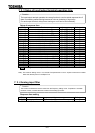
Input
terminal
Programmable controller
External +24 V
power supply
F
use
Fuse blowout
detector circuit
Internal +24 V power
supply (inverter)
Programmable controller
Inverter
F
S1
CC
S2
START
STOP
F/R switch