


L-4
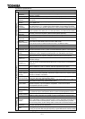
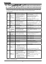
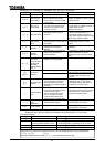
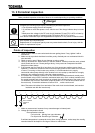
[Message] The following are messages only. No trip is developed.
Indication Contents Expected causes Countermeasures
ST-CC opened ST terminal is in open-circuit. Close ST-CC circuit.
Control circuit
undervoltage
Undervoltage between RO and
SO of control power supply
(when option is used for 22 kW
or lower type).
Measure supply voltage of control
power. If voltage is normal, it needs
repair service.
Main circuit
undervoltage
Undervoltage between R, S and
T of main circuit power supply.
Trouble of pre-charge circuit
or DC circuit fuse.
Measure supply voltage of main
circuit power. If voltage is normal, it
needs repair service.
Make a service call.
Retry indication
In retry operation.
Momentary power failure is
occurred.
If inverter automatically restarts
dozens of seconds later, it is
normal. Be careful of inverter in
retry status, because there is a fear
that it may suddenly restart.
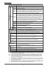
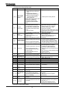
Frequency point
setting error
alarm
Points 1 and 2 of frequency
setting signal are set too close to
each other.
Set points 1 and 2 of frequency
setting signal apart from each
other.
Clear enabling
indication
If STOP key is pressed after trip
indication, this indication
appears.
Press STOP key once more for
resetting.
Emergency stop
enabling
indication
Stop operation is performed by
panel during automatic or
remote operation.
If STOP key is pressed, emergency
stop is executed. To cancel
emergency stop, press any other
key.
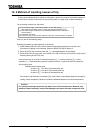
Alarm for setup
value error
(Error indication
and data are
alternately
displayed twice
each.)
Setup value error is detected in
reading out or writing data.
Check setup value for input error.
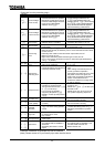
Under DC braking If message disappears dozens of
seconds later, it is normal. (Note)
DC braking
indication
Under motor shaft fixing control If message disappears by stop
command (ST-CC open), it is
normal.
Panel indication
overflow
Number to be shown on panel
such as frequency and so on
overflows figures of display.
(Number of overflowing digits is
indicated.)
For indication of frequency, set
multiplying rate () lower.
(Parameter setting that results in
overflow is of course valid.)
Communication
error
Various transmission errors
occur when computer is linked
up with inverter system.
Various transmission errors
occur in inverter to inverter
communication (slave side).
Time-out or trip in master side.
For countermeasures against
various transmission errors, refer to
the "Manual for communication".
Check the master inverter.
Parameter is
under
initialization.
Parameters are initialized to be
standard default values.
If message disappears dozens of
seconds later, it is normal.
In auto-tuning
Under auto-tuning. If message disappears several
seconds later, it is normal.
Note: In the case DC injection braking ON/OFF function is selected for an input terminal; if ""
disappears as a result of open-circuit between the terminal and CC, it is normal.
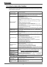
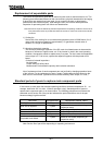
[Pre-alarm display]
Indication Contents Expected causes and countermeasures
Overcurrent alarm Same as (over-current)
Overvoltage alarm
Achieving PBR operation level
Same as (over-voltage)
P blink while PBR is operating is not an error.
Overload alarm Same as / (overload)
Overheat alarm Same as (overheat)
When two or more alarms occur at the same time, such the message as shown in the following blinks.
, , , , ,
Blinking indications appear in order of , , , from the leftmost place to right.