


F-74
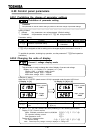
6.30.2 Using the RS485 port fitted as standard
With the standard serial RS485, you can connect each inverter to a higher-order control system
(host computer) to set up a data communications network between inverters. Also, you can
establish a data communications link between a computer and each inverter.
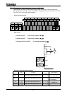
Serial RS485 connectors should be used to connect inverters to one another.
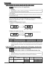
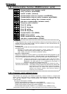
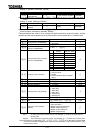
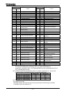
Data transfer specification
Item Specification
Interface RS485
Transmission path
specification
Half-duplex transmission [2/4-wire, bus architecture (A terminator needs
to be attached at each end of the system.)]
Transmission distance Up to 500 m (overall length of the cable)
Number of
connectable units
Up to 32 units (including a host computer)
Up to 32
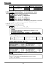
Synchronization mode Asynchronous transfer
Data transfer rate
Default setting: 9600 bps (parameter setting)
Selectable from among1200, 2400, 4800, 9600, 19200 and 38400 bps
Transmission character
ASCII code ... JIS X 0201 8-bit (ASCII)
Binary code ... Binary code, 8-bit fixed
Stop-bit length Received by inverter: 1 bit, sent from inverter: 2 bits
Error detecting system Parity: even/ odd/ non (parameter setting), check sum
Error correction function Not provided
Response monitoring Not provided
Transmission code Sending: 11 bit, Reception: 12 bit(with parity)
Transmission waiting
time setting
Possible
Others
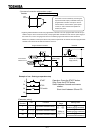
Action the inverter takes when an timeout occurs: tripping/alarm/no action
When alarm is selected, "" blinks at the left end of the control panel.
When tripping is selected, "" is displayed on the control panel.
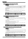
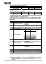
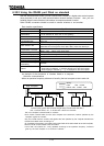
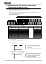
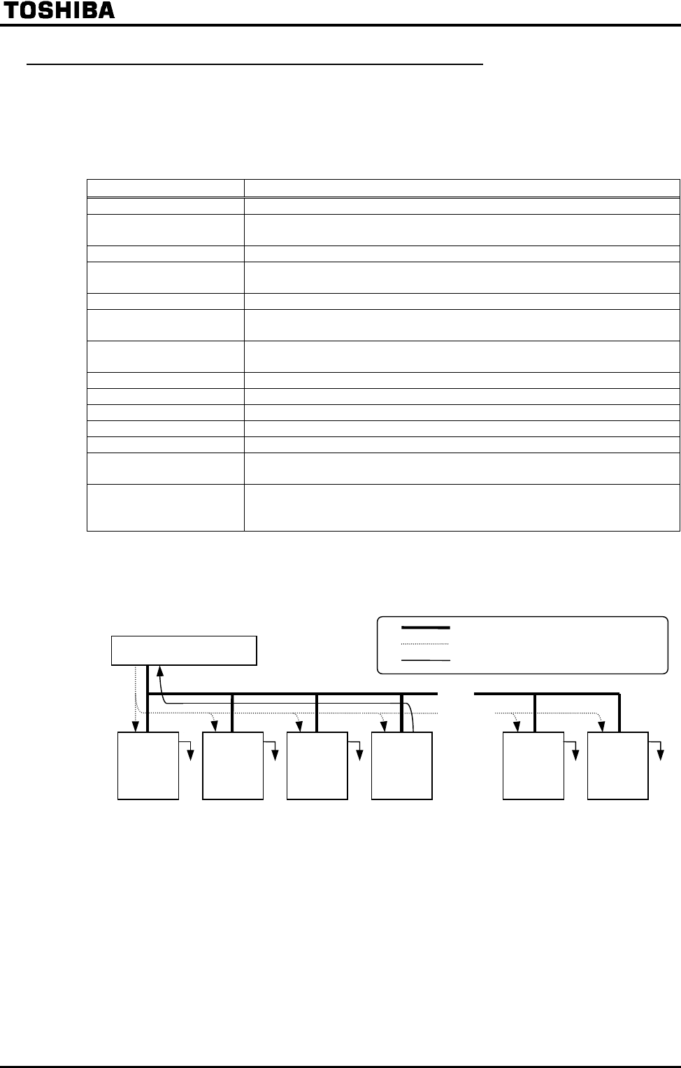
An example of the connection of inverters linked to a computer
Selective communications
When an operation frequency reference is isued by the host computer to the inverter No.
(IG)
Ignore: Inverters take no action if their numbers do not agree with the number specified in the
command( they ignore data received and get ready to receive the next data.)
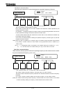
The host computer transmits data to inverters.
Each inverter receives data from the host computer and checks the number specified by the
computer against its number.
Only the inverter with the number that agrees with that specified by the computer decodes the
command and takes action according to it.
On completion of the action, the inverter returns the results of the action taken to the host computer,
with the inverter number added to this information.
In this case, the inverter No. 3 only operates according to the operation frequency command
given by the host computer to it across the network
.
Host computer
Wiring
Data Host Inverter
Return data Inverter Host
IG IG IGIGIG
Use a terminal board, etc., to divide each cable into branches.