


L-1
12. 1
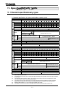
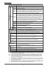
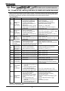
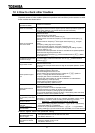
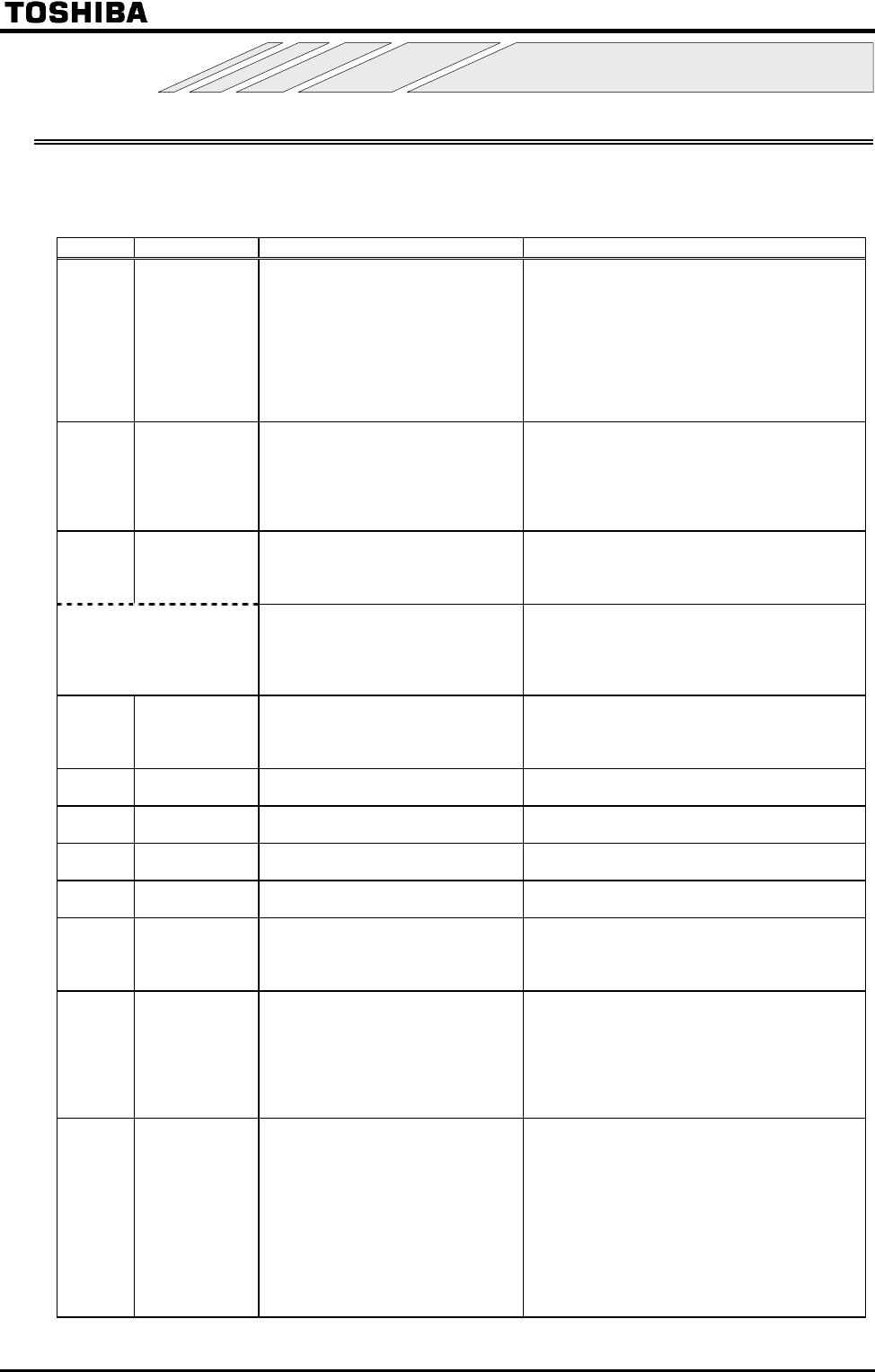
Cause of trip, warning indication (in detail and countermeasures)
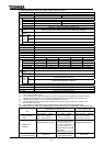
If there is something abnormal in the inverter or system, troubleshoot referring to the following table before
calling service. If the inverter needs to replace some part or the cause of the trouble cannot be removed by
the measures mentioned in the table, consult the dealer of the inverter about the trouble.
[Trip information]
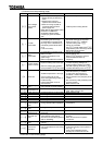
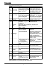
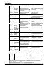
Indication Contents Expected causes Countermeasures
Overcurrent
during
acceleration
(DC current)
Acceleration time #1
is too short.
V/f parameter is improperly set.
Running motor is started during
momentary power failure.
Special motor (low impedance) is
used, isn't it?
Manual torque boost value(
) is large.
Output cable or motor falls into
ground-fault.
Extend acceleration time #1 .
Check V/f parameter.
Use
(Auto-restart) or
(Regenerative power ride-through control).
Raise carrier frequency
.
Decrease
setting value.
Check units and connections if there is
ground-fault or not.
Overcurrent
during
deceleration
(DC current)
Deceleration time #1 is too
short (in deceleration).
Running motor is started during
momentary power failure.
Output cable or motor falls into
ground-fault.
Extend deceleration time #1 .
Use
(Auto-restart) or
(Regen
erative power ride-through control).
Check units and connections if there is
ground-fault or not.
Overcurrent
during
fixed speed
(DC current)
Load rapidly varied.
Load is abnormal.
Output cable or motor falls into
ground-fault.
Reduce load variation.
Check loading unit.
Check units and connections if there is
ground-fault or not.
Note: ,,
originate
from causes other
than those
mentioned above.
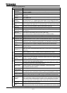
A device of main circuit is faulty.
Overheat protection is activated.
(5.5 to 15 kW, 30 kW or more)
Control voltage drop prevention function is
activated. (5.5 to 15 kW, 30 kW or more)
Make a service call.
Check operation of cooling fan.
Check cooling fan control mode parameter
.
Overcurrent
(loaded side
over-current at
start time)
Failure in wiring of main output
circuit or motor insulation.
Motor impedance is too low.
Check the wiring and motor insulation.
Properly set output short-circuit detection
parameter
and
.
U-phase arm
short-circuit
Something abnormal in some
device of main circuit (U-phase).
Make a service call.
V-phase arm
short-circuit
Something abnormal in some
device of main circuit (V-phase).
Make a service call.
W-phase arm
short-circuit
Something abnormal in some
device of main circuit (W-phase).
Make a service call.
Phase failure
(input side)
Phase lacking in input side of
main circuit.
Check connection of main input circuit for
phase lacking in input side.
(*1)
Phase failure
(output side)
Phase lacking in output side of
main circuit.
Check connection of main output circuit and
motor for phase lacking in output side.
Select output phase failure detection parameter
for checking.
Overvoltage
during
acceleration
Input voltage abnormally varied.
1:
Power-factor improving capacitor was
turned on/off.
2:
Some unit using thyrister is connected
with the same power supply line.
Running motor is started during
momentary power failure status.
Try to insert input reactor.
Use (Auto-restart) and
(Regenerative power ride-through control).
Overvoltage
during
deceleration
Deceleration time #1
is too short
(too much regenerated energy).
PBR resistance is too high.
Dynamic braking mode
is disabled.
Over-voltage stall protection
is
disabled.
Input voltage abnormally varied.
1
Power-factor improving capacitor was
turned on/off.
2
Some unit using thyrister is connected
with the same power supply line.
Extend deceleration time #1
.
Install dynamic braking resistor.
Decrease dynamic braking resistance.
(Also reset the
.)
Set dynamic braking mode parameter
properly.
Set over-voltage stall protection
properly.
Try to insert input reactor.
(*1): Presence or absence of parameter trip can be selected.
(Continued on the following page)
12.
Prior to service call
Trip information and countermeasures