


B-11
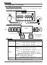
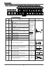
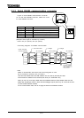
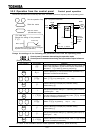
2.3.3 Serial RS485 communication connector
Figure of serial RS485 communication connector
To use the serial RS485 connector, detach the cover
for serial RS485 connector.
Signal name Pin number content
RXA 4 Same phase reception data(positive line)
RXB 5 Anti-phase reception data(positive line)
TXA 3
Same phase transmitting data(positive line)
TXB 6 Anti-phase transmitting data(positive line)
SG 2,8 Ground line of signal data
This table shows signal line of inverter side.
(Example: RXA signal is received by inverter.)
Never use pin-1(24Vdc) and pin-7(5Vdc).
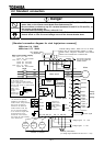
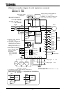
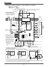
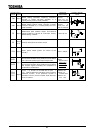
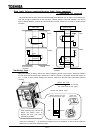
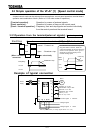
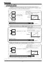
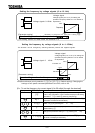
Connecting diagrams for RS485 communication
Note
Detach a communication line and the main circuit wiring 20cm or more.
Do not connect pin-1(24Vdc) and pin-7(5Vdc).
Twist the lines between RXA and RXB, between TXA and TXB by the twist pair cable.
Connect terminus resistance at the terminal (both ends) of a transmission way.
When you use it by 2 line type, please short-circuit between RXB and TXB, between RXA and TXA.
Master side reception(pin-4,pin-5) / slave side transmitting(pin-3,pin-6) lines may not connect at the time
of communication between inverters.
Fix the communication cable, and do not apply the stress to the RS485 connector.
Terminal resistor
100 -1/4W
VF-A7(slave)
Upper computer
or VF-A7(master)
cross each other straight
straight
VF-A7(slave) VF-A7(slave)
Pin-8
Pin-1