


B-2
Warning
Prohibited
Do not connect any device or unit with a built-in capacitor (noise filter, surge
suppressor, etc.) to output terminals (on the motor side), or it could cause the risk of
a fire.
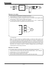
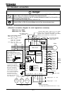
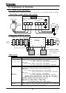
Prevention of radio noise
Prevent interference, such as radio noise, separately install and bind cables connected to the
power supply-side terminals (R/L1, S/L2 and T/L3) of the main circuit and those connected to the
motor-side terminals (U/T1, V/T2 and W/T3).
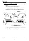
Power supply to the control and main circuits (for the 22kW and smaller models)
You want to keep the control circuit alive when the main circuit shuts off because of trouble or
tripping, you can use an optional power supply unit to supply power to the control circuit
separately from the main circuit.
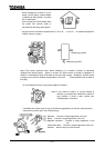
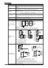
Notes on wiring
When connecting wires to the main circuit terminals, use crimp contacts because there is no
large space between terminals, and attach them in order so that they do not come into contact
with each other.
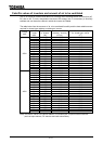
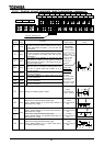
Be sure to ground the inverter by connecting wires of the following size or larger to the
grounding terminal G/E.(UL standard)
Voltage
class
Applicable motor
Grounding wire size
AWG(cross-section[mm
2
])
0.4 5.5kW
12(3.5)
7.5kW 10(5.5)
11 15kW 6(14)
18.5 22kW 4(22)
30 37kW
2(38)
45 55kW
2/0(60)
200V
75 90kW 4/0(100)
0.75 11kW 12(3.5)
15kW 10(5.5)
18.5kW 8(8)
22 30kW 6(14)
37 55kW 4(22)
75kW 2(38)
110 132kW 2/0(60)
160 220kW
4/0(100)
400V
280kW 300(150)
Refer to the table in 9.1 for wire sizes.
Wire sizes listed in 9.1 is for the case the wire length is below 30m. To use wires longer than
30m, you need larger cables than listed in 9.1.
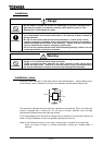
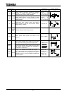
Tighten a terminal stand screw with specified bolting torque.
Recommended bolting torque for terminal stand
N mlbins
M3 0.5 4.4
M4 1.2 11
M5 2.4 21
M6 4.0 35
M8 8.0 71
M10 16 142
M12 32 283
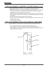
For the 200V 0.4~7.5kW
models and the 400V
0.75~7.5kW models, a
grounding screw (M5) is
provided in the wiring hole
cover, in addition to a
grounding terminal.