


B-10
Sink logic (minus common)/source logic (plus common)
... Switching I/O terminal
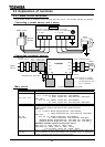
The input terminals of most control circuits are designed so that they turn on when a current flows out.
This type of logic is referred to as the "sink logic" (default setting). In Europe, however, the "source
logic" is widely adopted, in which the input terminals of control circuits turn on when a current passes
into them.
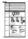
Switching logic
Before proceeding to wiring, switch logic without supplying power to the inverter. Switching between
the sink logic and the source logic at start-up or when the inverter is energized causes the inverter to
trip. In such a case, before resetting the inverter, make sure that the logic have been switched
correctly.
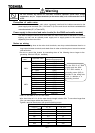
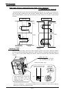
After switching logic, be sure to
attach the switch cover to
prevent the logic from being
switched by mistake.
If the error message (sink/source switching error) is displayed, check to be sure that the
sequence is normal, then reset the inverter.
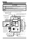
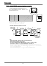
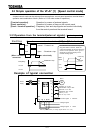
Sink logic
Inverter
Programmable
controller
common
common
output
input
input
output
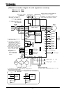
Source logic
Inverter
Programmable
controller
common
common
output
input
input
output
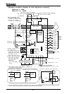
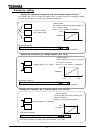
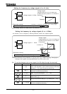
Detach the cover
sink source
Detach the switch cover
Switch between the sink
logic and the source logic.
Attach the
switch cover
(Push the mark and make
the cover slide to the right.)