


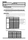
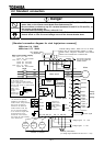
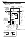
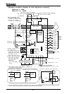
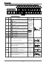
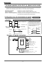
B-9
Terminal
symbol
Input /
output
Function
Electrical
specification
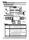
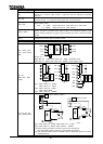
Inverter internal
circuit
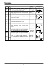
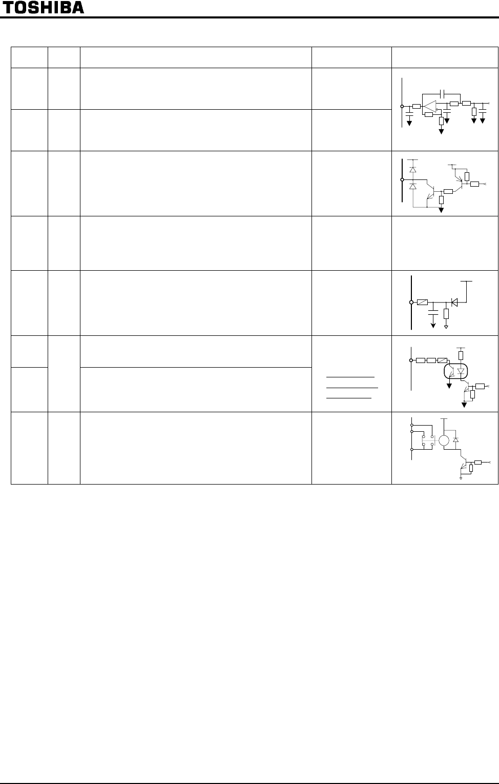
FM
Output
Multifunction programmable analog output. Factory
default setting: Operation frequency command.
Connect a 1mAdc full-scale ammeter or a
7.5Vdc(10Vdc)-1mA full-scale voltmeter.
1mA full-scale dc
ammeter or
7.5Vdc-1mA full-
scale dc voltmeter
AM
Output
Multifunction programmable analog output. Factory
default setting: Output current. Connect a 1mAdc
full-scale ammeter or a 7.5Vdc(10Vdc)-1mA full-
scale voltmeter.
1mA full-scale dc
ammeter or
7.5Vdc-1mA full-
scale dc voltmeter
FP
Output
Multifunction open collector output. This terminal
outputs pulses at 1.00 kHz to 43.20 kHz. Factory
default setting: 3.84kHz.
Max. 50 mA
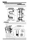
CC
Common
to I/O
Common terminal of the control circuit.
P24
Output
24Vdc power output (power for control of the
inverter).
24V
DC
-100mA
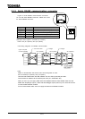
OUT1
Multifunction programmable open collector output.
The terminal has been set by default so as to detect
and output low-speed signal output frequencies.
OUT2
Output
Multifunction programmable open collector output.
The terminal has been set by default so as to detect
and outputs signals indicating the completion of
acceleration/ deceleration.
Open collector
output:
24Vdc-50mA
*Sink logic/
source logic
switchable
FLA
FLB
FLC
Output
Relay contact output. Contact rating: 250 Vac = -2
A (cos = 1), 30 Vdc-1 A and 250 Vac-1A (cos =
0.4). Used to detect the activation of the inverter's
protective function. If the protective function is
activated, FLA-FLC circuit is closed, while FLB-FLC
circuit is opened .
250Vac-2A
30Vdc-1A
:resistor load
250Vac-1A
:cos =0.4