


G-4
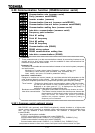
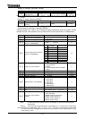
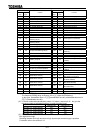
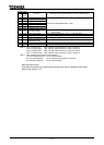
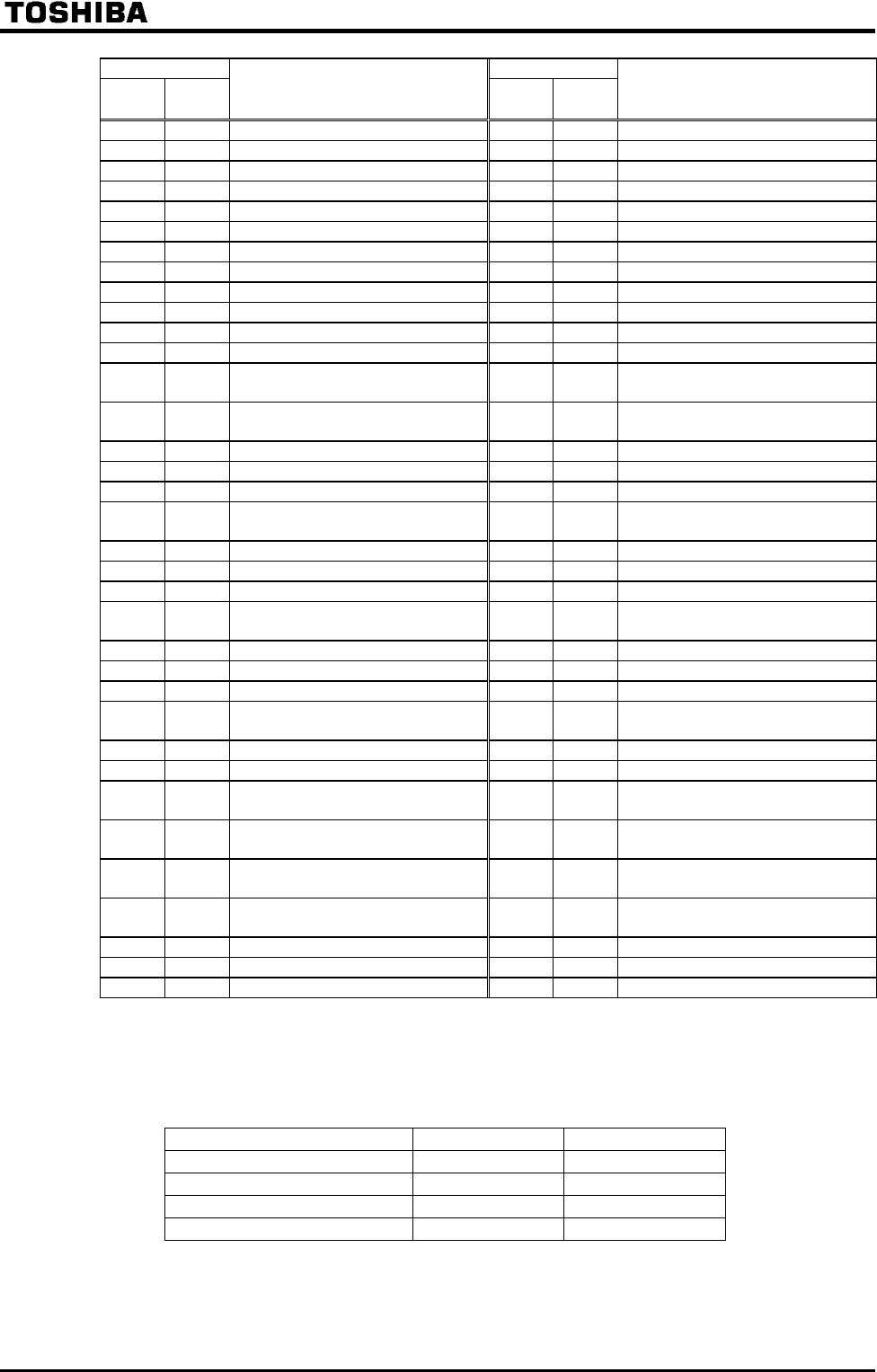
Table of contact input terminal function settings
Parameter setting Parameter setting
Positive
logic
Negative
logic
Function
Positive
logic
Negative
logic
Function
0 1 No assignment function 70 71 Reservation area(*3)
2 3 F: Forward operation command 72 73 Reservation area(*3)
4 5 R: Reverse operation command 74 75 Reservation area(*3)
6 7 ST: Standby 76 77 Reservation area(*3)
8 9 RES: Reset 78 79 Reservation area(*3)
10 11 S1: Preset-speed #1 80 81 Reservation area(*3)
12 13 S2: Preset-speed #2 82 83 Reservation area(*3)
14 15 S3: Preset-speed #3 84 85 Reservation area(*3)
16 17 S4: Preset-speed #4 86 87 Binary data write
18 19 Jog run 88 89 Up/down frequency (up) (*1)
20 21 Emergency stop 90 91 Up/down frequency (down) (*1)
22 23 DC injection breaking 92 93 Up/down frequency (clear)
24 25
Acceleration/deceleration
switching #1(*2)
94 95 PUSH-type run command
26 27
Acceleration/deceleration
switching #2(*2)
96 97 PUSH-type stop command
28 29 V/f switching #1(*2) 98 99 Forward/reverse selection
30 31 V/f switching #2(*2) 100 101 Run/stop command
32 33 Torque limit switching #1(*2) 102 103 Commercial power/INV switching
34 35 Torque limit switching #2(*2) 104 105
Frequency reference priority
switching
36 37 PID control OFF selection 106 107 VI/II terminal priority
38 39 Pattern group #1 108 109 Command terminal board priority
40 41 Pattern group #2 110 111 Parameter editing enabling
42 43 Pattern group #3 112 113
Control switching (torque,
position)
44 45 Pattern group #4 114 115 Deviation counter clear
46 47 Pattern run continuation signal 116 117 Position control forward limit LS
48 49 Pattern run trigger signal 118 119 Position control reverse limit LS
50 51 Forced Jog forward operation 120 121
Light load high-speed operation
enabling
52 53 Forced Jog reverse operation 122 123 Reservation area(*3)
54 55 Reservation area(*3) 124 125 Preliminary excitation
56 57 Reservation area(*3) 126 127
System consistent sequence
(BC: Braking command)
58 59 Reservation area(*3) 128 129
System-supporting sequence
(B: Brake release)
60 61 Reservation area(*3) 130 131
System-supporting sequence
(BA: Brake answer)
62 63 Reservation area(*3) 132 133
System-supporting sequence
(BT: Brake test)
64 65 Reservation area(*3) 134 135 Reservation area(*3)
66 67 Reservation area(*3)
68 69 Reservation area(*3)
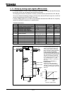
(*1): Valid when (Speed setting mode selection) is set at (Up-down frequency).
The frequency setting range is between 0.0 to (Upper limit frequency).
In this case, acceleration time is (Acceleration time #2), and deceleration time is
(Deceleration time #2).
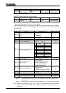
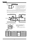
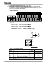
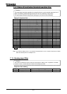
(*2): To switch acceleration/deceleration pattern, V/f pattern, torque limit #1 #4, give the
following signals to switching functions. (in case of positive logic)
switching #1 switching #2
Acc/dec, V/f, torque limit #1 OFF OFF
Acc/dec, V/f, torque limit #2 ON OFF
Acc/dec, V/f, torque limit #3 OFF ON
Acc/dec, V/f, torque limit #4 ON ON
(*3): Reservation area. Do not set at these functions.
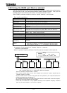
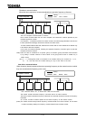
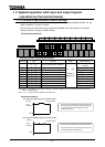
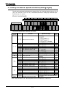
Sink logic/source logic
Switching between sink logic and source logic (input/output terminal logic) is possible.
For details, refer to the section 2.3.2.